Howdy
I'd like to know some clearer steps to get the USB working.
I have installed the VCP driver from FTDI. I tried both right-clicking on the port and bus .inf files, and choosing 'install', and also running the executable they provide....I wonder which of these 3 is correct.
When connected, and I flip the power switch on my x0x, I don't get any reaction from the computer. x0x lights do come on as normal, except in bootload mode, when no lights come on.
Do I need to be in any particular mode to have an effect? I have tried bootload, amongst others. I just don't get any response from the computer.
This is x0x 508 a kit from Ladyada and I had the USB pre-built.
Thanks.
-j
USB not working - no effect on pc
Moderators: altitude, adafruit_support_bill, adafruit, phono, hamburgers
Please be positive and constructive with your questions and comments.
-
guest
- Posts: 3155
- Joined: Fri Feb 17, 2006 5:35 am
Re: USB not working - no effect on pc
you should see it appear in your devices list
-
nogginj
- Posts: 39
- Joined: Sun Jul 08, 2007 11:37 pm
Re: USB not working - no effect on pc
Unfortunately, it does not show up in my devices in device manager - at least not under 'ports' or 'usb' (as it appears in this image from the manual at http://www.ladyada.net/make/x0xb0x/software/index.html):
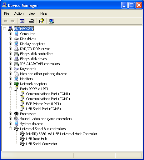
Again, the above is NOT what my computer shows.
The only thing that I could remotely find was, if I choose 'show hidden devices', I can see a device called 'serial' with a yellow exclamation point next to it. Clicking on this gives almost no useful or unique information. I am unsure if this was there beforehand.
My computer is WinXP Pro, but I tried first on Win 7.
Edit: Just tried on Mac OS X 10.5 (thanks to this thread http://forums.adafruit.com/viewtopic.ph ... 6&start=15), and I still don't see a device. c0ntr0l says:
Found the following serial ports: ['/dev/cu.Bluetooth-PDA-Sync', '/dev/cu.Bluetooth-Modem']
Still, I don't see anything about USB->Serial...I didn't have a lot of trouble soldering the I/O board that would make me think I fried the USB, but I suppose that is a possibility.
-
nogginj
- Posts: 39
- Joined: Sun Jul 08, 2007 11:37 pm
Re: USB not working - no effect on pc
Noticing this note from the I/O section of the fab manual:
Could this same optoisolator be goofing up my USB?
Off to the back to search for a 120ohm resistor...
Edit: Replaced R16 with 150ohm resistor...no effect. MIDI out still works, MIDI in does not work. USB still does not work (I realise now the opto isolator probably has 0 to do with this).
This is likely happening to mine, right now. I am able to send MIDI sync and note data, but I am not getting anything into the x0x."Note: in batch #6 we've started to notice that the optoisolators are possibly made to a different specification. If MIDI out and MIDI thru are working but MIDI in is not, try upping R16 to 120 or 150 ohms! "
Could this same optoisolator be goofing up my USB?
Off to the back to search for a 120ohm resistor...
Edit: Replaced R16 with 150ohm resistor...no effect. MIDI out still works, MIDI in does not work. USB still does not work (I realise now the opto isolator probably has 0 to do with this).
-
guest
- Posts: 3155
- Joined: Fri Feb 17, 2006 5:35 am
Re: USB not working - no effect on pc
the ftdi drivers are probably not getting installed properly
but in case its a hardware thing
i think there are voltage readouts for the ftdi chip in the forums
you might want to check that they are correct
i suggest using google to search the forums
but in case its a hardware thing
i think there are voltage readouts for the ftdi chip in the forums
you might want to check that they are correct
i suggest using google to search the forums
-
nogginj
- Posts: 39
- Joined: Sun Jul 08, 2007 11:37 pm
Re: USB not working - no effect on pc
on three separate machines though? I hope this is the case, but I'm not seeing why one would think that at this point.the ftdi drivers are probably not getting installed properly
still searching for the ftdi voltage map...
Edit: MIDI in works over the MIDI THRU port...(found via the troubleshooting section)...maybe I need exactly 120ohm resistor, not 100 or 150 to make midi in port work. Either way I can live with relabelling MIDI THRU to MIDI IN.
I have found that there is a pin on the USB chip to check for 3.3v and I will do that tomorrow. If there is anything else I can check USB wise please let me know.
Thanks
-j
Edit 2: Found the voltage map of the FTDI chip you mention: http://forums.adafruit.com/viewtopic.php?p=9136
with the micro out and usb connected
pin / voltage
1 / 0
2 / 5
3 / 5
4 / 3.3
5 / 3.3 with data
6 / 3.3
7 / 3.3 with data
8 / 0 with data
9 / 0
10 / 5
11 / 0
12 / 0
13 / 5
14 / 5
15 / 5
16 / 0
17 / 0
18 / 5
19 / 5
20 / 5
21 / 5
22 / 5
23 / 5
24 / 5
25 / 5
26 / 5
27 / clock
28 / clock
29 / 0
30 / 5
31 / 0
32 / 0
-
guest
- Posts: 3155
- Joined: Fri Feb 17, 2006 5:35 am
Re: USB not working - no effect on pc
if midi in didnt get fixed with a lower value resistor
there is probably something else wrong
you can apply 5v and see if the serial line toggles
there is probably something else wrong
you can apply 5v and see if the serial line toggles
-
nogginj
- Posts: 39
- Joined: Sun Jul 08, 2007 11:37 pm
Re: USB not working - no effect on pc
Well I tried a higher value resistor. I went from 100ohm -> 150ohm at R16. Would there still be reason to try 120ohm?
Also when you say apply 5v, and check the serial line, are you talking about on the USB chip? I'm not sure where to apply the 5v and where to check the toggle.
Also, as I mentioned, Midi in does work using the MIDI thru port, so the functionality is there just not the connection it sounds like.
Thanks
-J
-
guest
- Posts: 3155
- Joined: Fri Feb 17, 2006 5:35 am
Re: USB not working - no effect on pc
have you checked out those usb voltages
-
nogginj
- Posts: 39
- Joined: Sun Jul 08, 2007 11:37 pm
Re: USB not working - no effect on pc
i was a little worried about constantly taking the microcontroller + eeprom out, so I wanted to pick up an IC extractor for safety, and also, that 120ohm resistor to try and fix the MIDI IN bug.
I picked those up tonight and I plan on getting into the sucker (as well as a friends sick mpc 1000) after some rest.
thanks alot for pointing out those voltages, that's just what i wanted to check. i think i have found the datasheet (to check the pinout) for the ft232 here http://www.datasheetarchive.com/pdf-dat ... 87697.html
-
nogginj
- Posts: 39
- Joined: Sun Jul 08, 2007 11:37 pm
Re: USB not working - no effect on pc
Got some voltages here, micro out, eeprom out, usb plugged in, x0x powered on:
Looking at the datasheet, that looks about right. I've got ~5v at the VCC's, 0 at GND's, and a little over 3.3 at 3.3out.
The main differences I see between mine and yours:
- I've got 5 at pin1, you've got 0 (this is EESK Clock to EEPROM...maybe cause I took EEPROM out...don't think it's relevant).
- I've got 0 at 10, where you've got 5 ... according to datasheet this is 'SLEEP' pin..."Goes Low during USB Suspend Mode. Typically used to power-down an external TTL to RS232 level converter i.c. in USB -> RS232 converter designs." (interesting)
- you've got 5 at pin 15...from datasheet "PWREN# - OUT - Goes Low after the device is confi gured via USB, then high during USB suspend. Can be used to control power to external logic using a P-Channel Logic Level MOSFET switch. Enable the Interface Pull-Down Option in EEPROM when using the PWREN# pin in this way."
- Ive got 0 at 21... "DTR# OUT Data Terminal Ready Control Output / Handshake signal"
- I've got 0 at 23... "RTS# OUT Request To Send Control Output / Handshake signal"
- I've got 0 at 25... "TXD OUT Transmit Asynchronous Data Output"
- I've got 5 at 32... "EECS I/O EEPROM – Chip Select. For 48MHz operation pull EECS to GND using a 10k resistor. For 6MHz operation no resistor is required. Tri-State during device reset."
Now, I'm no USB chip expert, but none of that looks very strange, does it? All looks good, as far as I can tell.
What do yall make of it?
Edit: just tried with EEPROM in and made no changes
Code: Select all
Pin- voltage
---
01- 4.72
02- 5.06
03- 5.11
04- 3.43
05- 0.03
06- 3.69
07- 0.02
08- 0
09- 0
10- 0
11- 0
12- 0
13- 5.11
14- 5.11
15- 0
16- 0
17- 0
18- 4.72
19- 4.72
20- 4.72
21- 0
22- 4.72
23- 0
24- 4.72
25- 0
26- 5.11
27- 1.65
28- 5.06
29- 0
30- 5.11
31- 0
32- 4.72The main differences I see between mine and yours:
- I've got 5 at pin1, you've got 0 (this is EESK Clock to EEPROM...maybe cause I took EEPROM out...don't think it's relevant).
- I've got 0 at 10, where you've got 5 ... according to datasheet this is 'SLEEP' pin..."Goes Low during USB Suspend Mode. Typically used to power-down an external TTL to RS232 level converter i.c. in USB -> RS232 converter designs." (interesting)
- you've got 5 at pin 15...from datasheet "PWREN# - OUT - Goes Low after the device is confi gured via USB, then high during USB suspend. Can be used to control power to external logic using a P-Channel Logic Level MOSFET switch. Enable the Interface Pull-Down Option in EEPROM when using the PWREN# pin in this way."
- Ive got 0 at 21... "DTR# OUT Data Terminal Ready Control Output / Handshake signal"
- I've got 0 at 23... "RTS# OUT Request To Send Control Output / Handshake signal"
- I've got 0 at 25... "TXD OUT Transmit Asynchronous Data Output"
- I've got 5 at 32... "EECS I/O EEPROM – Chip Select. For 48MHz operation pull EECS to GND using a 10k resistor. For 6MHz operation no resistor is required. Tri-State during device reset."
Now, I'm no USB chip expert, but none of that looks very strange, does it? All looks good, as far as I can tell.
What do yall make of it?
Edit: just tried with EEPROM in and made no changes
-
guest
- Posts: 3155
- Joined: Fri Feb 17, 2006 5:35 am
Re: USB not working - no effect on pc
there are three options
1. the chip is bad
2. there is a short someplace
3. the drivers arent working with your computer
even if the drivers arent installed
it should still show up as an unkown device
in your device manager
you can take a look at all the devices before plugging in the x0x
and see if any new ones appear
if its a ladyada kit
then the usb was tested before shipping out
is it possible it got damaged in shipping or storage
pins that seem suspect from your voltage readings
pins 5 and 7
make sure they arent shorted to ground or neighboring pins
and that they connect to the usb jack
pin28
make sure its not shorted to 5v
or any neighboring pins
im guessing a lot of those other pins are different
because the chip hasnt initialized
the crystal may not be oscillating right as well
double check all the solder joints
and look really closely at the usb chip
to make sure there arent any solder balls kicking around
-
nogginj
- Posts: 39
- Joined: Sun Jul 08, 2007 11:37 pm
Re: USB not working - no effect on pc
Thanks for the reply.
I'm still hesitant to believe #3 because I've tried 3 different computers and 3 different os's. Also, like you said, it should at least 'duh nun' and the computer should pick up SOMETHING having been connected.
Yea it is a ladyada kit from run 5 I think (serial 508).
I do really appreciate your guesses as to the suspect pins...I will check these tomorrow. Is there anyway I can check the crystal (I do have a scope)?
The main voltage regulator was a little loose at one point and eventually broke off. I suppose that could have fried it, but there's so much going on between the regulator and the chip, I'm still hoping that's not the case.
-
guest
- Posts: 3155
- Joined: Fri Feb 17, 2006 5:35 am
Re: USB not working - no effect on pc
wow youve got a scope
that changes things
probe the oscillator pins
one should be making a sinewave at 6MHz
check the pins labeled with data
and see if they have any data on them
that changes things
probe the oscillator pins
one should be making a sinewave at 6MHz
check the pins labeled with data
and see if they have any data on them
-
nogginj
- Posts: 39
- Joined: Sun Jul 08, 2007 11:37 pm
Re: USB not working - no effect on pc
howdy
i probed the xtl2 and the outermost pins do give me very very slight, very very fast sinewaves, albeit at different dc offsets....1v vs ~0.8v. I hope I am seeing them correctly, I had to turn my scope to the highest setting for triggering (in the nano-second range), and I'm just a little unsure how to use it properly (salvaged from the old phone company...this thing is huge).
I would like some clarification while I keep trying to track this problem down:
1) Regarding x0x 'modes'...which mode should I be in to test? Will the USB be recognised in ANY mode (ie. pattern - sync out or midi play), or does it have to be in 'computer control' or 'bootload' mode?
2) Should I still be removing the main x0x microchip while performing some of these tests?
Thanks
EDIT: Just tested 'data' pins, and I do get what looks like a sine wave, maybe changing frequency, similar to the one I was getting from the XTL2 (minus the dc offset), on all of those pins.
Please be positive and constructive with your questions and comments.