Enclosure for the x0xb0x and x0xi0

Discuss mods, hacks, tweaks, etc.

Moderators: altitude, adafruit_support_bill, adafruit, phono, hamburgers

Please be positive and constructive with your questions and comments.
Locked
User avatar
maxtim
 
Posts: 213
Joined: Wed Oct 12, 2005 5:01 pm

Enclosure for the x0xb0x and x0xi0

Post by maxtim »

Image


Image


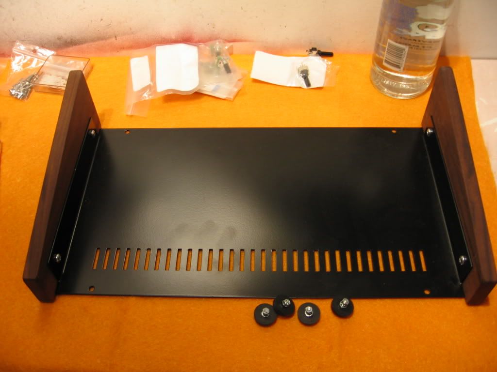
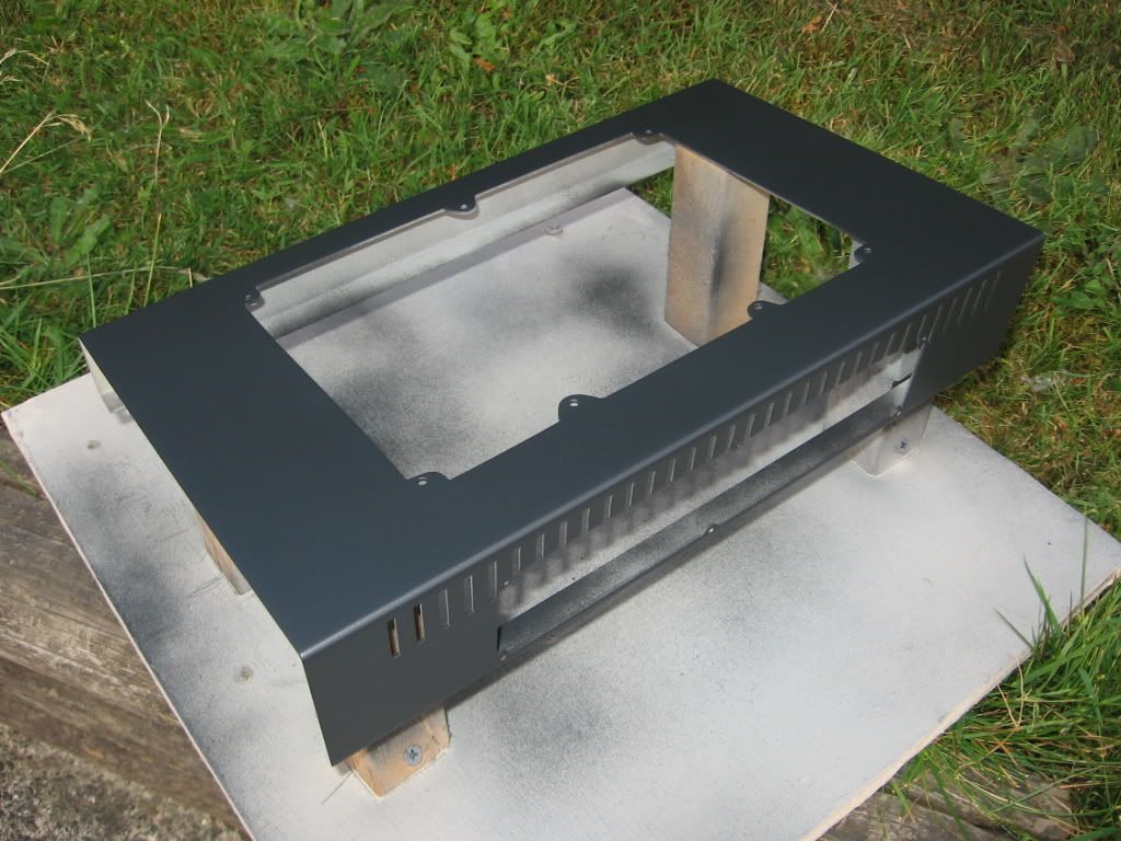
Manufacturer’s site:
http://www.hammondmfg.com/dwg16.htm#10degree
Model #:
1456PH1WHCWW
DIGI-KEY item page (Canadian):
http://search.digikey.com/scripts/DkSea ... H1WHCWW-ND

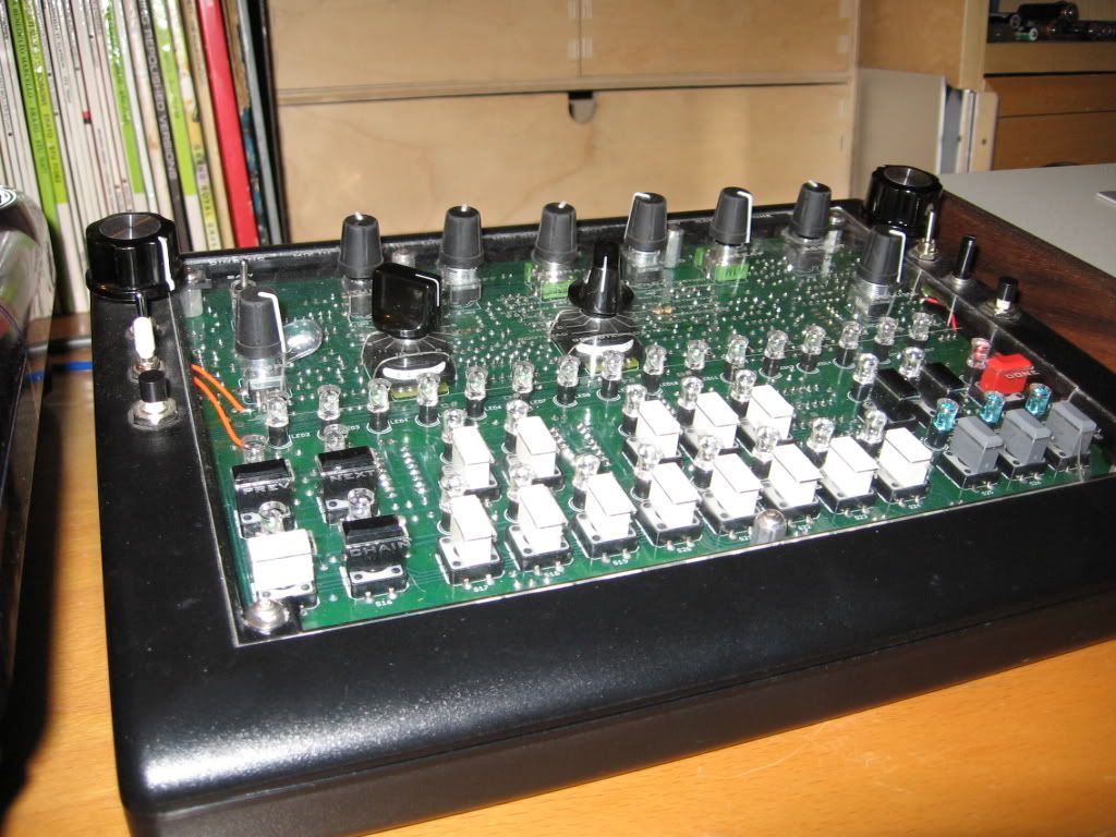
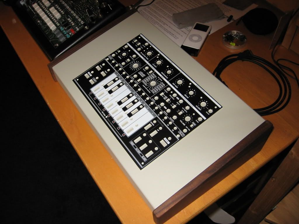
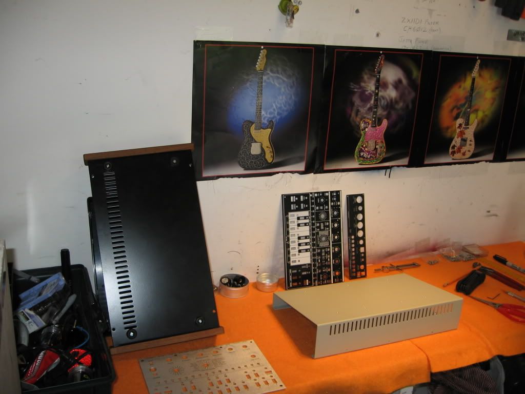
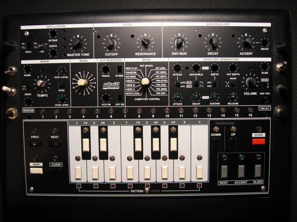
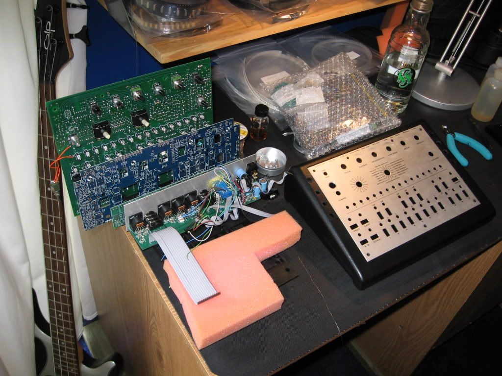
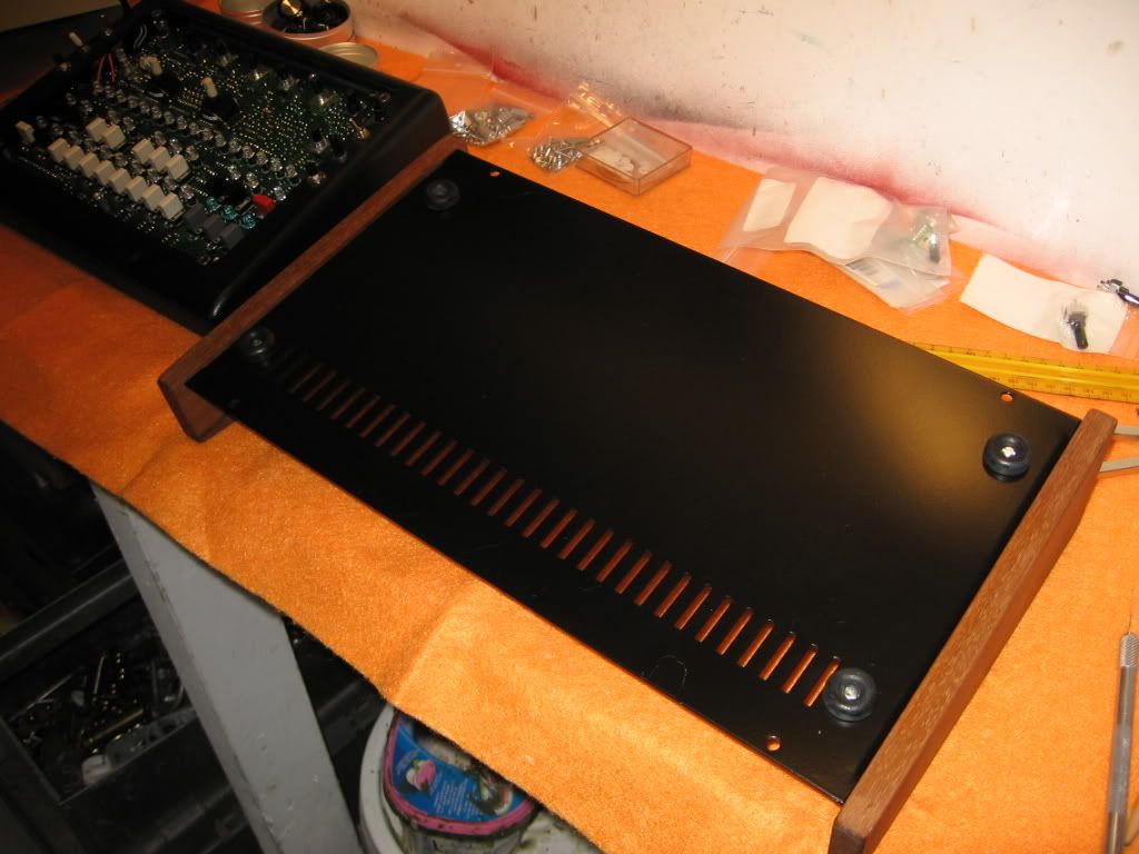
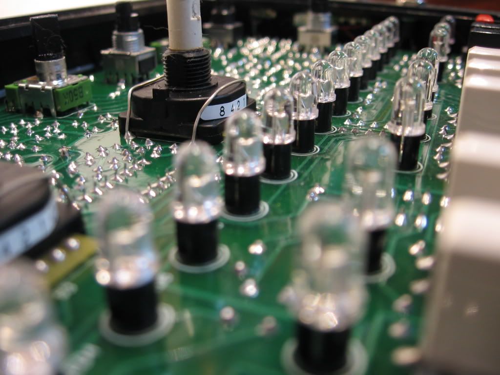
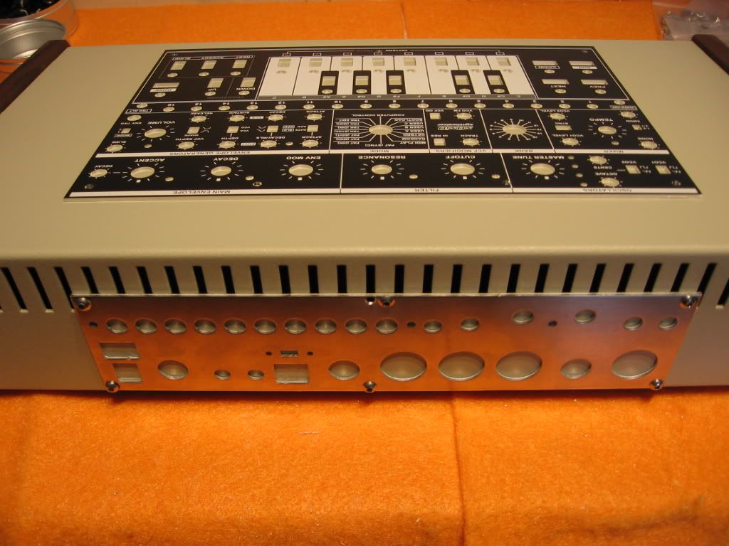
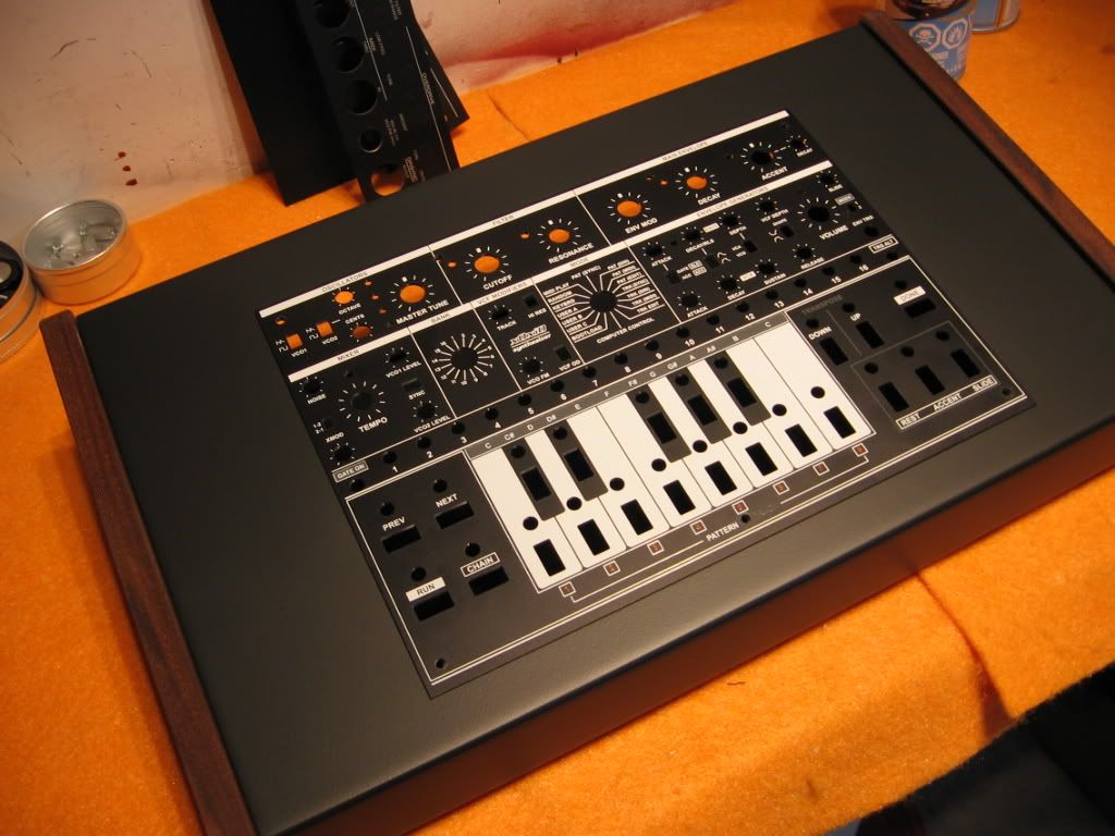
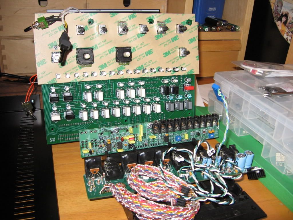
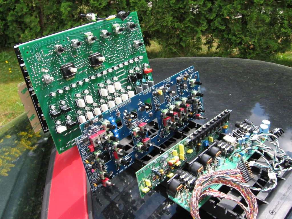
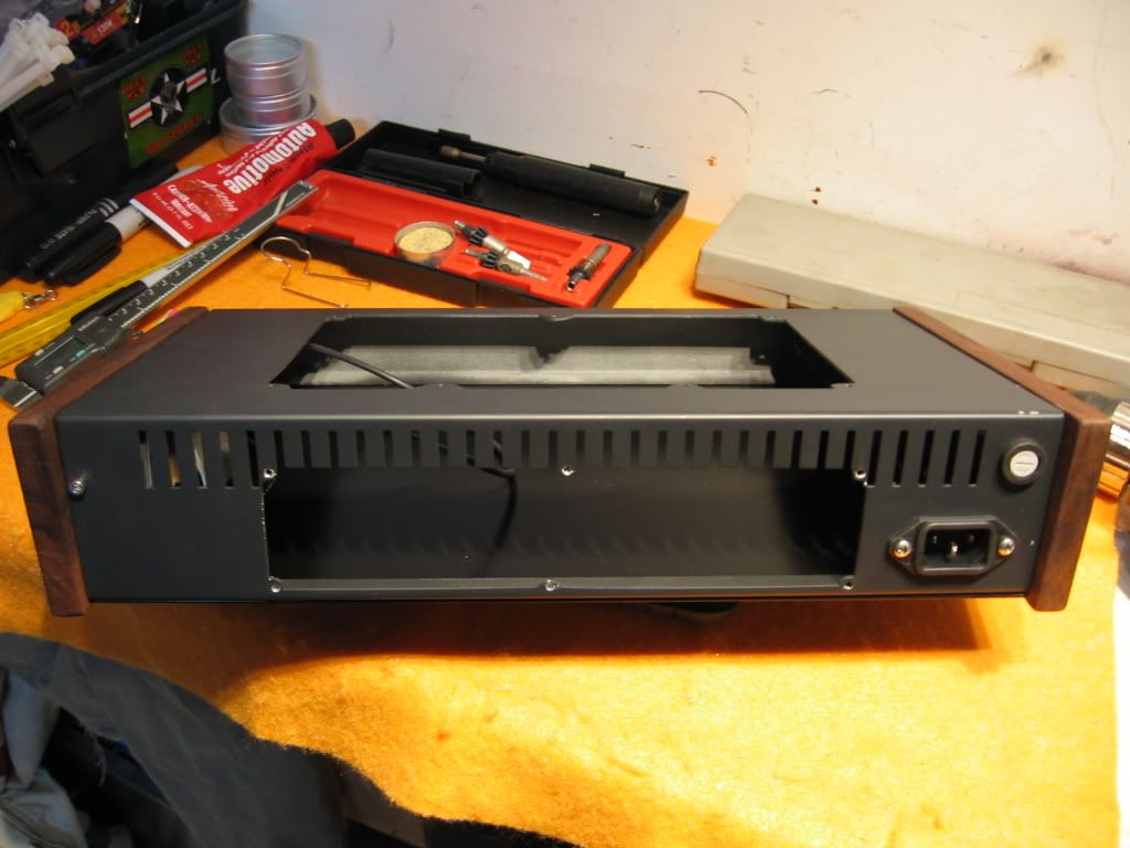
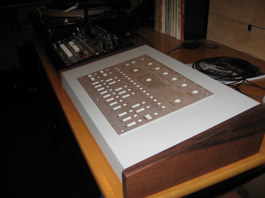
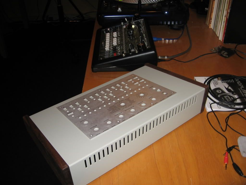
The wonderful electronics of the x0xb0x and x0xi0 in an appropriate enclosure :?:
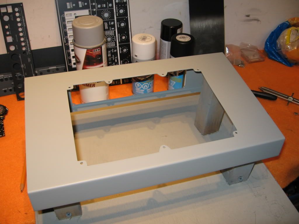
With walnut side panels for that retro look (though can be painted for a more modern appeal)

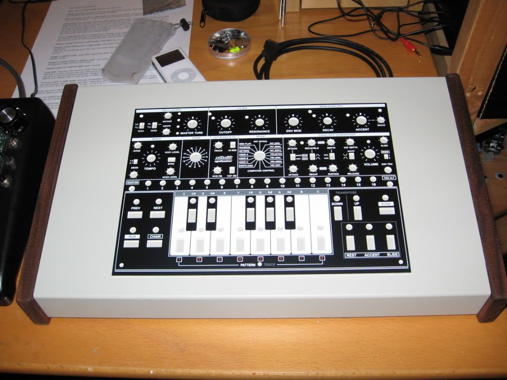
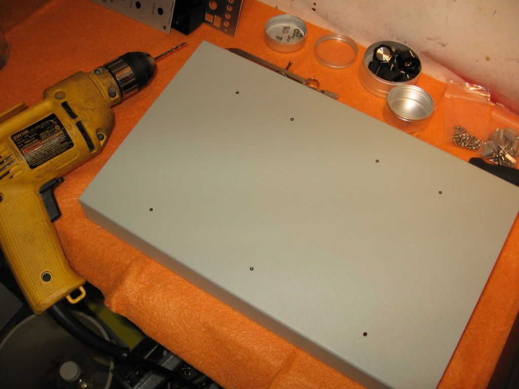
I plan on bringing the controls from the rear of the box (overdrive +) to the face.
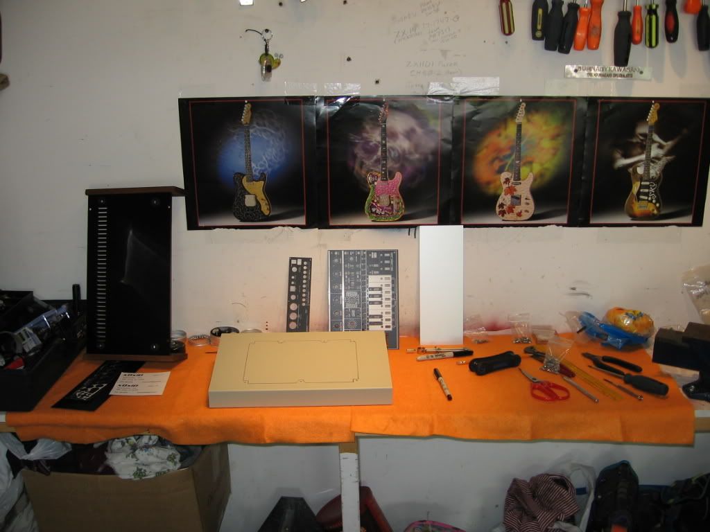
I also want to add a few other mods and some performance control buttons.
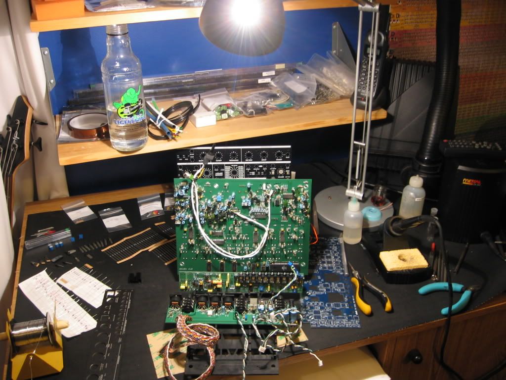
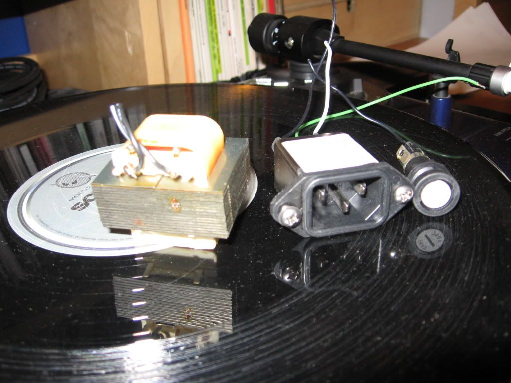
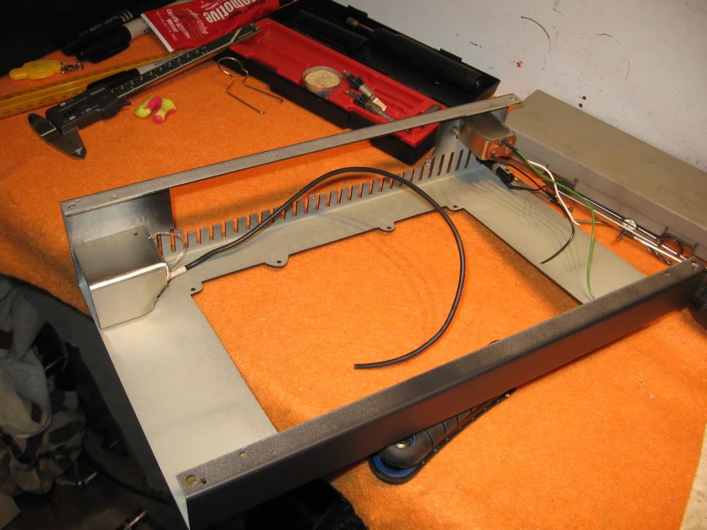
This box gives enough room for lots of fun additions: battery pack maybe, on board sound, I was even pondering putting the power supply in the box with an AC plug for a standard cord (not recommending :oops: (potentially dangerous :twisted: ))


FUN :D

eil
 
Posts: 440
Joined: Sun Aug 31, 2008 11:09 pm

Re: Enclosure for the x0xb0x and x0xi0

Post by eil »

maxtim wrote:I was even pondering putting the power supply in the box with an AC plug for a standard cord (not recommending :oops: (potentially dangerous :twisted: ))
It'll be fine if you do it properly, but if it were me, I dunno that it would be worth all the effort.

User avatar
maxtim
 
Posts: 213
Joined: Wed Oct 12, 2005 5:01 pm

Re: Enclosure for the x0xb0x and x0xi0

Post by maxtim »

It'll be fine if you do it properly, but if it were me, I dunno that it would be worth all the effort.
The 9VAC adapter is simply a single transformer.
It can be fused on the input.
It would have to be bolted to the case with a bracket.
A metal grounded shield would have to be built around it to eliminate noise.

Not easy, but it would sure make this box a Pro level unit. :mrgreen:

User avatar
maxtim
 
Posts: 213
Joined: Wed Oct 12, 2005 5:01 pm

Re: Enclosure for the x0xb0x and x0xi0

Post by maxtim »

Image


Image

User avatar
hamburgers
 
Posts: 1058
Joined: Wed Dec 21, 2005 8:25 pm

Re: Enclosure for the x0xb0x and x0xi0

Post by hamburgers »

what are those red wires on the left for?

User avatar
maxtim
 
Posts: 213
Joined: Wed Oct 12, 2005 5:01 pm

Re: Enclosure for the x0xb0x and x0xi0

Post by maxtim »

what are those red wires on the left for?
If I remember correctly, those are for the tempo LED switch.
I installed 10mm ultra-bright white LED that looked great for performance, but was annoyingly bright (11,000 mcd), so I hooked it up to a toggle switch and a resistor to allow me to run it at either full or partial intensity.

I re-cut the hole in the aluminum panel to accomodate the large LED, but when I installed the clear plastic top panel, I bent the LED over to shine across the PCB. You can see the top of the LED in the first picture, laying behind the tempo knob.

I am not sure what I am going to do for the x0xi0 installtion though. I may keep the LED, or change it to something else.
I have a few new ideas brewing for LED arrangements/colors when I upgrade into the new enclosure.

User avatar
maxtim
 
Posts: 213
Joined: Wed Oct 12, 2005 5:01 pm

Re: Enclosure for the x0xb0x and x0xi0

Post by maxtim »

Recieved the x0xi0 kit today.
W0w! The panel is sweet.
Now time for some cuttin' and drillin' to make this happen.
I think I'll post progress of the build in this thread.

Image

Image

User avatar
maxtim
 
Posts: 213
Joined: Wed Oct 12, 2005 5:01 pm

Re: Enclosure for the x0xb0x and x0xi0

Post by maxtim »

Worked a little on the x0b0x x0x0io today.
Gutted x0xb0x 111 and removed some of the mods.
Set-up for the PCA build.
Checked the new faceplate out on the old box.
I managed to get the new enclusure front and rear plates drilled, tapped and mounted.
I also drilled and installed a set of proper feet to the bottom plate of the new enclosure (it came with rubber stick-on feet)

Tommorow I will be cuttting.
Thinking of paint.
How does black with a white boarder sound? To follow the design/style of the x0xio faceplate.

Image


Image


Image


Image


Image


Image


Image


Image


Image
Last edited by maxtim on Wed Jul 29, 2009 11:05 am, edited 2 times in total.

User avatar
maxtim
 
Posts: 213
Joined: Wed Oct 12, 2005 5:01 pm

Re: Enclosure for the x0xb0x and x0xi0

Post by maxtim »

Did the cuttin' today .
and bought flat-black and white paint.
Also started on the sanding.


Cutting
Image


Done

Image
Last edited by maxtim on Wed Jul 29, 2009 12:01 pm, edited 2 times in total.

User avatar
maxtim
 
Posts: 213
Joined: Wed Oct 12, 2005 5:01 pm

Re: Enclosure for the x0xb0x and x0xi0

Post by maxtim »

After a day at work, this was a great way to wind down.

The original beige paint on the aluminum was rough finish, full for deep pits and bubbles so......
Lots of sanding. A good hour of luv at least as painting is all about the prep.
Then I did a test spray on some scrap metal to ensure the primer and paint was compatible. Good to go.
Built a painting jig.
Then on with the primer. Turned out perfect.

Sanded and on the jig ready for primer.Image

Ready for black (tomorrow)
Image
Last edited by maxtim on Thu Apr 07, 2011 9:31 am, edited 2 times in total.

User avatar
maxtim
 
Posts: 213
Joined: Wed Oct 12, 2005 5:01 pm

Re: Enclosure for the x0xb0x and x0xi0

Post by maxtim »

On with the black paint.
I had to do it inside (what a stink) because the cottonwood was blowing like crazy around these parts.
Almost flawless.
One little pesky peice of lint.
I'll have to wait for the paint to cure and do a little sanding and try again.
It looks fantastic back in the case.
Next step will be masking for the white boarders.
I'll have to put it aside for a few days to wait for the paint to thoroughly cure before masking.

Image

Image
Last edited by maxtim on Wed Jul 29, 2009 12:02 pm, edited 1 time in total.

User avatar
maxtim
 
Posts: 213
Joined: Wed Oct 12, 2005 5:01 pm

Re: Enclosure for the x0xb0x and x0xi0

Post by maxtim »

Today I sanded the flaw in the first and put a second coat of paint on.
Last edited by maxtim on Wed Jul 29, 2009 12:02 pm, edited 2 times in total.

User avatar
maxtim
 
Posts: 213
Joined: Wed Oct 12, 2005 5:01 pm

Re: Enclosure for the x0xb0x and x0xi0

Post by maxtim »

I have moved on with the electronics on the x0xi0 rear panel.
I completed the PCA as far as I could (missing parts, documentation discrepancies and such) I will complete all the x0xi0 kit before I send the list to Brian (bcbox).
I test fitted the rear panel and both PCAs into the custom enclosure and found that I had to cut the original x0xb0x rear PCA in 3 places to clear the mounting screws. One of the cuts passed through a trace on the PCA, so I had to wire route it.
I re-wired all of the modifications that I am going to keep from my original build.
I started on sourcing parts (panel mount) and wiring to move the rear controls (distortion etc.) to the face of the box.
I re-wired all of the original ribbon cable connectors on the rear x0xb0x PCA with upgraded wire and connectors.
I gathered together all that I need for the in-box power supply including a great AC plug with a built in power filter.
Tonight I move onto the front x0xi0 PCA build. I want to complete the x0xi0 ASAP, so I can get all of the kit issues sorted and the circuits completed.
cut the insulation panel


Image


Image


Image


Image


Image
Last edited by maxtim on Wed Jul 29, 2009 11:06 am, edited 1 time in total.

User avatar
maxtim
 
Posts: 213
Joined: Wed Oct 12, 2005 5:01 pm

Re: Enclosure for the x0xb0x and x0xi0

Post by maxtim »

I completed the front x0xi0 and test fit the new PCA stack under the front panel. Excellent!

Did some testing and replacing of LEDs Green of 2 types-sequencer with alt. on the1/4 and run, Cyan -x0xi0, blue-RAS, white-keyboard, pink-octave up/down, purple-next/prev, red-done

I did some paint work on the face and back plate of the x0xi0 so that there would be no bare metal showing (blend into the black case with no border line (my plates sit on the surface, not recessed into the case like the original x0xb0x.

Sent a list of kit and documentation omissions and errors to “bcbox”

I think of how to arrange and drill the holes for many pots, switches and buttons that are going to be mounted on the front of the case (12 planned so far). And about how I am going to tackle the mounting of the new 120V power input and internal transformer. Thinking of how I want the white paint on the case to be, and how to label the new controls.


Image
Last edited by maxtim on Wed Jul 29, 2009 12:03 pm, edited 3 times in total.

User avatar
maxtim
 
Posts: 213
Joined: Wed Oct 12, 2005 5:01 pm

Re: Enclosure for the x0xb0x and x0xi0

Post by maxtim »

I completed the fabrication and initial installation of the on-board power supply.
The box is now substantially heavy and feels very solid.

I hope to get in a little time tomorrow to do a test install of all the board stacks as it will be much easier to correct mistakes and make adjustments now before all the wiring goes in between all the PCAs.
I already know of a couple of clearance issues on the front x0xi0 PCA.
And also, I need to find out how the extra offset of the new box front plate is going to affect the control height and LED heights.

Then I can plan out the placement of the new controls on either side of the main plate and start drilling some holes.

Unfortunately I have already made a few scratches and marks on my perfectly painted enclosure, so I have bought some more paint and will do some sanding and a final coat once the metalwork is finalized.
Then I can mask and paint the white lines that will bring it all together


Image


Image
Last edited by maxtim on Wed Jul 29, 2009 12:04 pm, edited 2 times in total.

Locked
Please be positive and constructive with your questions and comments.

Return to “x0xm0dz”