Hello Adafruit people! I just wanted to share a project I've been working on. Much of the core componentry came from your lovely shop and your tutorials proved quite helpful.
Over the last couple months I have been coding my own open source temperature control program for the Arduino MEGA 2560. I call it notorious PID. It incorporates a 20x4 character LCD for display, a rotary encoder with pushbutton for user input, Dallas OneWire DS18B20 temperature sensors, and a unique control algorithm inspired largely by the work of Elco Jacobs on [url=http://"http://www.elcojacobs.com/uberfridge/"]UberFridge[/url] and [url=http://"http://www.brewpi.com/"]brewPI[/url]. It also has data logging capabilities and supports end-user made CSV temperature programs (lists of steps: run at X temp for Y duration) via an SD card slot. This makes it possible to create custom temperature profiles for different fermentations that include things like temperature ramping, diacetyl rests and cold crashing. For a more complete description, check the README at my GitHub repository.
I've written a couple libraries that may be of use to other Arduino coders out there. The dallas temperature library was creating a huge problem for the speed of my code with its hard coded delay so I've written my own wrapper class for DS18B20 OneWire temperature sensors. I've also written some versatile templated functions to add EEPROM read/write functionality to my project.
Most of my work the last couple weeks has been focused on tweaking the control algorithms and determining various tuning parameters (unique to each chamber/fridge/freezer). There are a few small bugs that do not affect overall performance that I have to clear up. Until I do so, I've currently released it as prerelease v0.9.0 on GitHub. Can anyone point me in the right direction for creating some images of my wiring layout?
notorious PID source via GitHub: https://github.com/osakechan/notoriousPID
notorious PID fermentation temperature control
Moderators: adafruit_support_bill, adafruit
Please be positive and constructive with your questions and comments.
-
mboehm
- Posts: 9
- Joined: Fri Jun 06, 2014 12:46 pm
notorious PID fermentation temperature control
Last edited by mboehm on Tue Aug 05, 2014 11:06 pm, edited 2 times in total.
-
adafruit_support_mike
- Posts: 67485
- Joined: Thu Feb 11, 2010 2:51 pm

Re: notorious PID fermentation temperature control
Awesome!
For schematics, take a look at Fritzing: http://www.fritzing.org/ We use it a lot for diagrams in our tutorials.
For schematics, take a look at Fritzing: http://www.fritzing.org/ We use it a lot for diagrams in our tutorials.
-
mboehm
- Posts: 9
- Joined: Fri Jun 06, 2014 12:46 pm
Re: notorious PID fermentation temperature control
Wiring schematic up!
notorious PID - Logical Schematic @ GitHub
I tried to post the image, but forum bbcode does not seem to allow re-sizing and I am far to lazy to re-scale and upload another copy.
Any tips for improving it? Also...I'd like to make something similar for the wiring of my power circuitry. Problem is, I can't seem to find any mention of power outlet parts for Fritzing. I know I could possibly go through the trouble to make my own part but it seems like a great deal of effort when I could be working on code. Any alternatives?
Last edited by mboehm on Sun Aug 10, 2014 2:37 pm, edited 2 times in total.
-
adafruit_support_mike
- Posts: 67485
- Joined: Thu Feb 11, 2010 2:51 pm
Re: notorious PID fermentation temperature control
Looks good!mboehm wrote:Wiring schematic up!
It's always good to have both an image and a written list of signal names/connections:mboehm wrote:Any tips for improving it?
- LCD pin 1 (RESET) to Arduino pin #7
- LCD pin 2 (CLK) to Arduino pin #12
- etc
The image gives you a general overview of the circuit, the list gives you the details you want when connecting a single wire.
I don't know of any Fritzing parts for power connections off the top of my head. You might want to check over in their forums to see if anyone has suggestions.mboehm wrote:Also...I'd like to make something similar for the wiring of my power circuitry. Problem is, I can't seem to find any mention of power outlet parts for Fritzing.
-
mboehm
- Posts: 9
- Joined: Fri Jun 06, 2014 12:46 pm
Re: notorious PID fermentation temperature control
List of connections is a good tip and I will include it!
I did end up throwing together a power outlet part for fritzing. It is largely hand traced with the pen tool from a stock image i found on the web (so it may not be perfectly symmetrical). An image of the svg I made:

Link to the new readme section:
nPID Power Circuitry @ Github -- https://github.com/osakechan/notoriousP ... -schematic
I did end up throwing together a power outlet part for fritzing. It is largely hand traced with the pen tool from a stock image i found on the web (so it may not be perfectly symmetrical). An image of the svg I made:
Link to the new readme section:
nPID Power Circuitry @ Github -- https://github.com/osakechan/notoriousP ... -schematic
-
adafruit_support_mike
- Posts: 67485
- Joined: Thu Feb 11, 2010 2:51 pm
Re: notorious PID fermentation temperature control
Nice! I'll bet a lot of people will end up using that. ;-)
-
mboehm
- Posts: 9
- Joined: Fri Jun 06, 2014 12:46 pm
Re: notorious PID fermentation temperature control
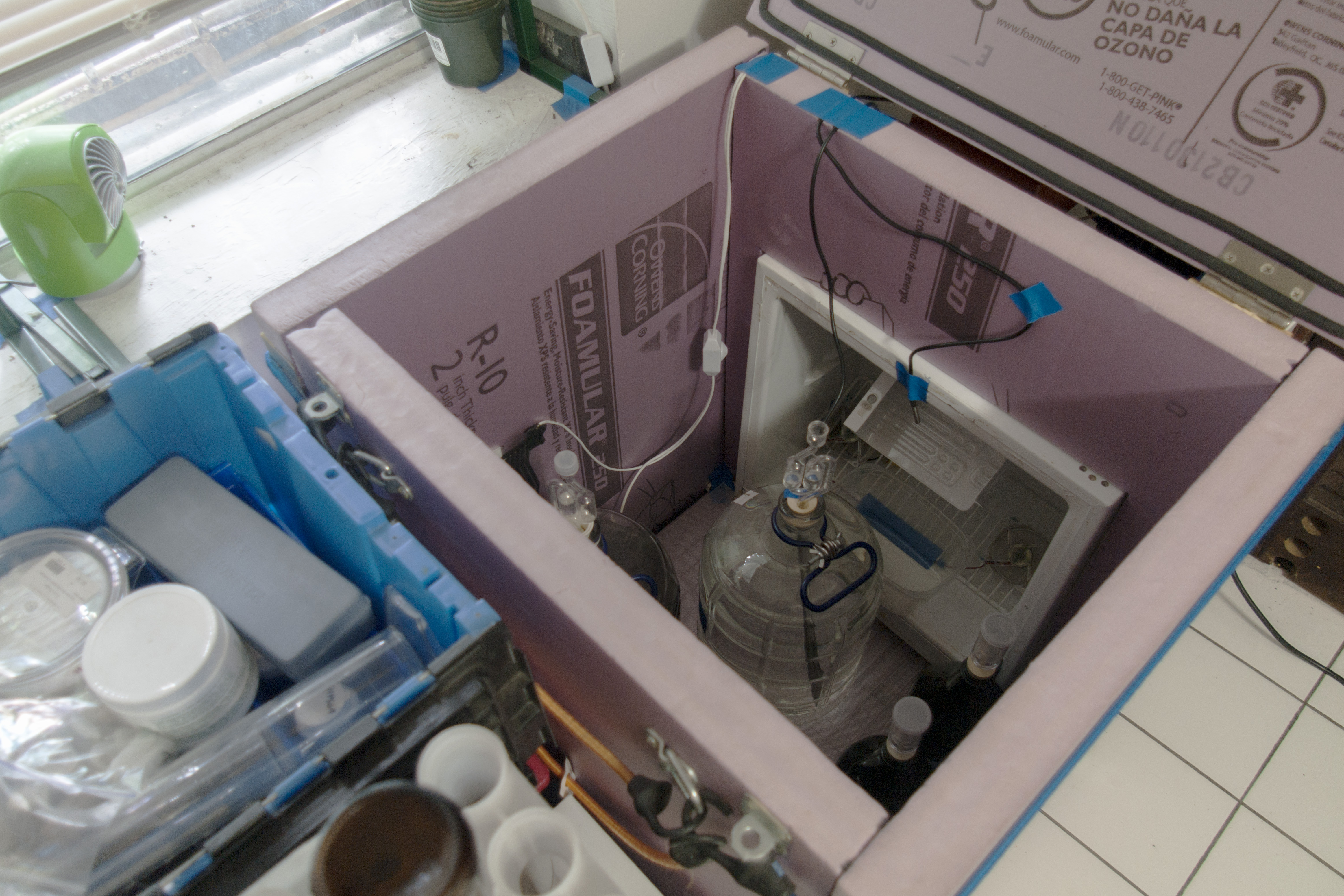
It's photo time!
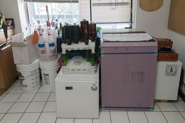
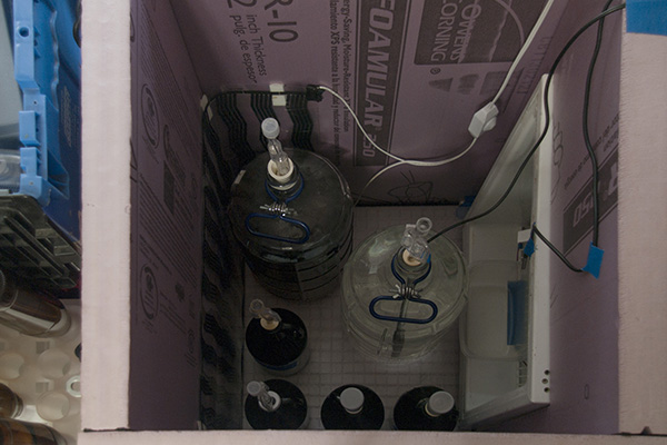
The chamber is constructed of 2" thick solid foam insulation. Cooling is provided by a diminutive 1.7 cu. Ft. dorm fridge obtained for free. Heating is provided by a bit of aging flexwatt also obtained for nil. There are a pair of 80mm CPU fans for air circulation. I've seen similar builds elsewhere on homebrewtalk that were glued together for a more permanent installation. I'll be moving at the end of the month and I built the chamber with this move in mind. I installed a couple of hooks on the front and back and bungees hooking into these are what hold it all together. The lid is hinged with a pair of hasps for locking it down. Gorilla Glue is perfect for use on this kind of foam and with clamps gives a strong bond. In one of the shots you can see a double wall of weather stripping along the inside lid of the chamber. Intersecting faces of the walls also have this stripping to create a reasonably airtight seal.
The second fridge in the overall shot of the space is not part of the chamber (it houses my culture library).
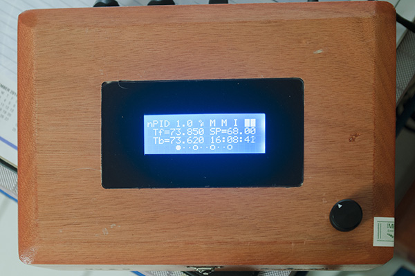
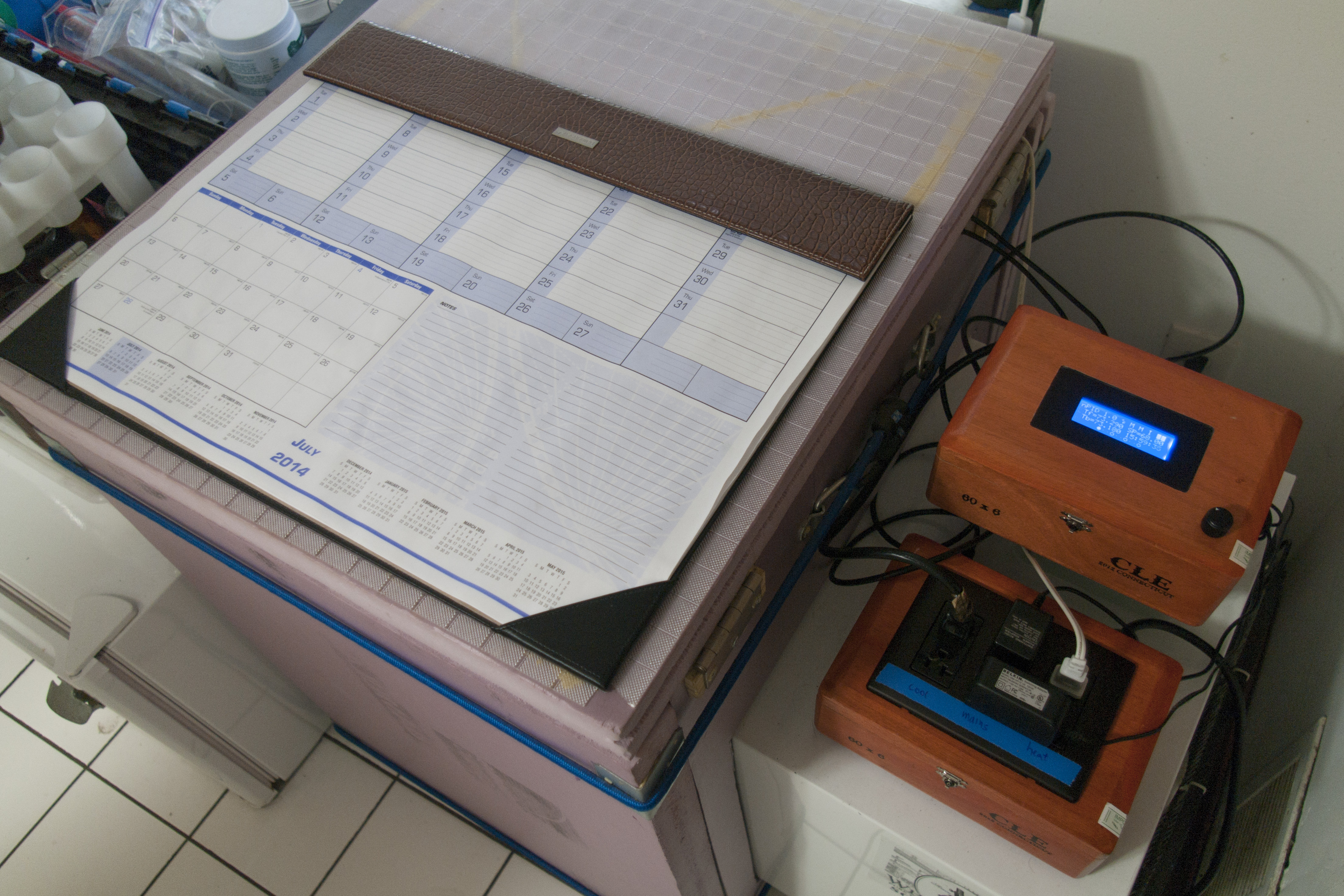
The temperature controller is housed in a pair of c.i.g.a.r boxes purchased for cheap on eBay. An ethernet cable with RJ45 connectors connects the two boxes. Logic circuitry has been isolated as much as possible from high voltage power circuitry. The LCD resides behind black vinyl masking on 1/8" acrylic that sits flush into the top of the box and also hides the LCD's mount screws.


The chamber is constructed of 2" thick solid foam insulation. Cooling is provided by a diminutive 1.7 cu. Ft. dorm fridge obtained for free. Heating is provided by a bit of aging flexwatt also obtained for nil. There are a pair of 80mm CPU fans for air circulation. I've seen similar builds elsewhere on homebrewtalk that were glued together for a more permanent installation. I'll be moving at the end of the month and I built the chamber with this move in mind. I installed a couple of hooks on the front and back and bungees hooking into these are what hold it all together. The lid is hinged with a pair of hasps for locking it down. Gorilla Glue is perfect for use on this kind of foam and with clamps gives a strong bond. In one of the shots you can see a double wall of weather stripping along the inside lid of the chamber. Intersecting faces of the walls also have this stripping to create a reasonably airtight seal.
The second fridge in the overall shot of the space is not part of the chamber (it houses my culture library).
The temperature controller is housed in a pair of c.i.g.a.r boxes purchased for cheap on eBay. An ethernet cable with RJ45 connectors connects the two boxes. Logic circuitry has been isolated as much as possible from high voltage power circuitry. The LCD resides behind black vinyl masking on 1/8" acrylic that sits flush into the top of the box and also hides the LCD's mount screws.


-
adafruit_support_mike
- Posts: 67485
- Joined: Thu Feb 11, 2010 2:51 pm
Re: notorious PID fermentation temperature control
That's a nice build.. clearly functional, and it also looks good.
I like the way you mounted and masked the LCD.. that's a technique I plan to steal for my own projects down the line. ;-)
I like the way you mounted and masked the LCD.. that's a technique I plan to steal for my own projects down the line. ;-)
Please be positive and constructive with your questions and comments.