ICE TUBE Second digits are DIM
Moderators: adafruit_support_bill, adafruit
Please be positive and constructive with your questions and comments.
-
neutron spin
- Posts: 163
- Joined: Sat Apr 03, 2010 6:11 pm

Re: ICE TUBE Second digits are DIM
Also a Russian power supply for VFD clock without big iron on the mains using small ferrite transformer in a switching power supply...note 5 volts fed to tube filament...Just eliminate the bridge rectifier and supply DC to the circuit if you choose...70's technology at it's best!...my oh my how different we all can be if we try hard enough! 

- Attachments
-
- power supply no transformer
- PS no xfmr.jpg (138.43 KiB) Viewed 3554 times
-
neutron spin
- Posts: 163
- Joined: Sat Apr 03, 2010 6:11 pm
Re: ICE TUBE Second digits are DIM
All kidding aside, I would use a TSC428 MOSFET driver chip and use the Microcontroller to drive it at some frequency in the firmware if a new design were to be done...much more efficient and more flexible than using the 5 volt DC regulator to drive the filament ...
-
jarchie
- Posts: 615
- Joined: Sun Jun 24, 2012 2:16 pm

Re: ICE TUBE Second digits are DIM
Thank you for looking up those schematics, and I'm glad to see you rejoin the discussion.
Although I'm still a DC-works-fine-on-the-IV-18 fanatic, I do believe that these tubes were designed for use with alternating current on the filament. But my certainty in that fact is less than before.
The diagram below is from the IV-18 documentation. There is a dotted line (grid symbol) attached on one end (pin 1) of the filament, implying it would have a positive charge. I suppose the filament "grid" would be the larger metal attachment on the right hand side. Such a feature might be intended to reduce cathode poisoning by absorbing free electrons.
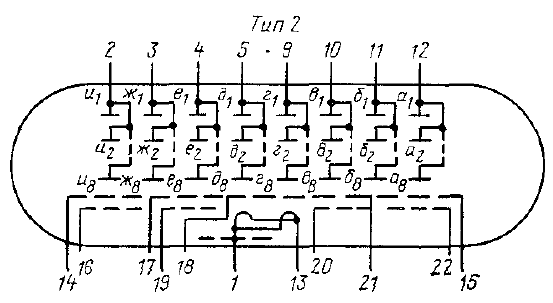
That being said, my explanation seems improbable. The dotted line on pin 1 must have some other meaning. But why would one side of the filament be drawn differently?
Although I'm still a DC-works-fine-on-the-IV-18 fanatic, I do believe that these tubes were designed for use with alternating current on the filament. But my certainty in that fact is less than before.
The diagram below is from the IV-18 documentation. There is a dotted line (grid symbol) attached on one end (pin 1) of the filament, implying it would have a positive charge. I suppose the filament "grid" would be the larger metal attachment on the right hand side. Such a feature might be intended to reduce cathode poisoning by absorbing free electrons.
That being said, my explanation seems improbable. The dotted line on pin 1 must have some other meaning. But why would one side of the filament be drawn differently?
-
wbp
- Posts: 260
- Joined: Mon Mar 07, 2011 1:18 pm

Re: ICE TUBE Second digits are DIM
Apparently not...that is all I will say on this subject...
Seriously, you have shown us several schematics and other references, and we have done actual testing and practical results. If you want to add a transformer or some other means of using AC to drive the filaments, great, but I would have to ask, "why bother"? It has been shown that this doesn't do anything to improve the display if the filament voltage is in the correct range.
What is the problem you are trying to solve? If it's uneven display brightness, the original topic of this thread, there is a simple solution, and it doesn't require adding any additional components. Just replace R3 with a jumper.
William
-
jarchie
- Posts: 615
- Joined: Sun Jun 24, 2012 2:16 pm
Re: ICE TUBE Second digits are DIM
I just realize that I've hijacked this thread by asking if the IV-18 was really, in fact, designed for AC. I can't speak for neutron spin, but I suspect his recent posts were were an attempt to answer that question.What is the problem you are trying to solve? If it's uneven display brightness, the original topic of this thread, there is a simple solution, and it doesn't require adding any additional components. Just replace R3 with a jumper.
Anyhow....you're absolutely right, William. Replacing R3 with a jumper does solve the dim digit problem in practice, and this discussion probably should have ended there. My apologies.
-
neutron spin
- Posts: 163
- Joined: Sat Apr 03, 2010 6:11 pm
Re: ICE TUBE Second digits are DIM
OK.... you must be correct but I DO have an EE and have over 45 years of design experience but do not want to meddle in your affairs but an open mind is a valuable trait. Have you done over 20,000 hours of testing and determined your method will meet the tube designer's criteria for life expectancy of the device? Your test methods are crude at best. If you have the "time" look up the term "Filament Notching"....wbp wrote:Apparently not...that is all I will say on this subject...
Seriously, you have shown us several schematics and other references, and we have done actual testing and practical results. If you want to add a transformer or some other means of using AC to drive the filaments, great, but I would have to ask, "why bother"? It has been shown that this doesn't do anything to improve the display if the filament voltage is in the correct range.
What is the problem you are trying to solve? If it's uneven display brightness, the original topic of this thread, there is a simple solution, and it doesn't require adding any additional components. Just replace R3 with a jumper.
William
Just make it work and that is enough? Fine but could you tell me the difference between the heating or the thermionic effect of 5 volts AC RMS and 5 Volts DC? on the tube filament...Will this result in any negative appreciable operating characteristics? Go to your "laboratory" and apply each of these voltages to a pure resistive load. Measure the temperature of the load and power of each test and report the results. I am sure if you counted the electrons that would be another test result as well.I am glad you are not designing any components on the space shuttle...lol...OH I forgot that is retired now like I am now on this subject....peace be with you son...
-
neutron spin
- Posts: 163
- Joined: Sat Apr 03, 2010 6:11 pm
Re: ICE TUBE Second digits are DIM
I believe that is an extra grid in the tube to reduce it's µ or trans-conductance. The tube is nothing more than a triode and will amplify any stray voltages on the grid(s) and stabilize the tube to prevent self-oscillation or the "Dynatron Effect". If you find an IV-18 that has a higher than design gain, try putting your hand near the glass envelope and you will see the digits get brighter. This extra "Grid" has no other function but reduce the tubes secondary emission from the filament similar to the suppressor grid in a tetrode tube. It also may help with any gradient effect on the display. If the tub's gain was not controlled the brightness would flicker even with the 60 HZ noise from fluorescent lights and the capacitance effect from close objects. Of course I may be wrong...you know?jarchie wrote:Thank you for looking up those schematics, and I'm glad to see you rejoin the discussion.
Although I'm still a DC-works-fine-on-the-IV-18 fanatic, I do believe that these tubes were designed for use with alternating current on the filament. But my certainty in that fact is less than before.
The diagram below is from the IV-18 documentation. There is a dotted line (grid symbol) attached on one end (pin 1) of the filament, implying it would have a positive charge. I suppose the filament "grid" would be the larger metal attachment on the right hand side. Such a feature might be intended to reduce cathode poisoning by absorbing free electrons.
That being said, my explanation seems improbable. The dotted line on pin 1 must have some other meaning. But why would one side of the filament be drawn differently?
- Attachments
-
- The hahaha effect on your clock
- Potential-gradient-effect.jpg (70.86 KiB) Viewed 4019 times
-
jarchie
- Posts: 615
- Joined: Sun Jun 24, 2012 2:16 pm
Re: ICE TUBE Second digits are DIM
That seems like a good theory. I'm not sure how the extra grid works in that capacity though. I don't see anything between the grids and plates.This extra "Grid" has no other function but reduce the tubes secondary emission from the filament similar to the suppressor grid in a tetrode tube.
Neat idea. I'll have to try that!If you find an IV-18 that has a higher than design gain, try putting your hand near the glass envelope and you will see the digits get brighter.
I'm struggling to understand the point here. If you're claiming that, for some unforeseen reason, driving the filament with DC might reduce tube life, then I completely agree. But if you're claiming that driving the filament with DC is likely to reduce tube life, then I remain skeptical.look up the term "Filament Notching" ... could you tell me the difference between the heating or the thermionic effect of 5 volts AC RMS and 5 Volts DC?
As I understand it, filament notching is mainly a problem at high current densities, but the filament on the IV-18 barely glows. In regard to thermionic effects, I believe electromigration is also a problem only at high current densities. Filament voltage remains well below the maximum negative cathode to grid voltage, so cathode poisoning due to plating seems unlikely.
I think the main concern for VFDs is phosphor life, and the choice of AC or DC on the filament should not affect phosphor life so long as brightness is consistent.
I'm also puzzled by the purpose of the brightness gradient photo. The caption is "The hahaha effect on your clock," but the photo is neither an Ice Tube Clock nor even an IV-18. I don't understand the relevance.The hahaha effect on your clock
I'll conclude with the following quote from another discussion.
All things considered, replacing R3 with a jumper still seems like an acceptable solution for a DIY bedroom clock.We use VFs on several of our products, all with DC filament drive. Maybe 10,000 or so by now, some in the field for 15-20 years now, usually running 24/7. I don't know of any filament failures. DC seems to work fine.
The filaments run at much lower tempearture than light bulbs, and light bulbs that run dull red have enormous expected lifetimes.
-
neutron spin
- Posts: 163
- Joined: Sat Apr 03, 2010 6:11 pm
Re: ICE TUBE Second digits are DIM
OK...good luck with your clock....The Mikoyan-Gurevich MiG-25 designers would be proud of you using their tubes in your bedroom clock...jarchie wrote:That seems like a good theory. I'm not sure how the extra grid works in that capacity though. I don't see anything between the grids and plates.This extra "Grid" has no other function but reduce the tubes secondary emission from the filament similar to the suppressor grid in a tetrode tube.
Good theory but not really totally true...There are Russian manuals that show the physical construction of the tube but the grid shown on the data sheet i think is just a "theoretical grid"...just showing that there is some control of tube gain to keep it from oscillating...I have seen a few tubes actually go into oscillation...strange but true!
Neat idea. I'll have to try that!If you find an IV-18 that has a higher than design gain, try putting your hand near the glass envelope and you will see the digits get brighter.
They all do not do that...I would say less than 10 percent do...
See report from the Air force Wright Patterson A.B. WRDC-TR-90-4075...just one example but there are many of the effect of D.C. both on vacuum tube filament and incandescent lamps. It is the chemistry of the filament wire that determines how bad it can be and testing will show if they are degraded. These In-18 filaments seem to be quite strong but who knows?....only the engineer that designed the tubes...I will try to see if he is still alive...probably not but i am sure there is documentation.look up the term "Filament Notching" ... could you tell me the difference between the heating or the thermionic effect of 5 volts AC RMS and 5 Volts DC?
I'm struggling to understand the point here. If you're claiming that, for some unforeseen reason, driving the filament with DC might reduce tube life, then I completely agree. But if you're claiming that driving the filament with DC is likely to reduce tube life, then I remain skeptical.
One example see report WRDC-TR-90-4075
As I understand it, filament notching is mainly a problem at high current densities, but the filament on the IV-18 barely glows. In regard to thermionic effects, I believe electromigration is also a problem only at high current densities. Filament voltage remains well below the maximum negative cathode to grid voltage, so cathode poisoning due to plating seems unlikely.
Unknown filament chemistry but perhaps you are correct....
I think the main concern for VFDs is phosphor life, and the choice of AC or DC on the filament should not affect phosphor life so long as brightness is consistent.
Yes they will get dimmer over time...some designs DO step up filament voltage to deal with the fading...that is why they are run at minimum operating parameters at first to prolong phosphor life....
Just a pun....that was an experiment on a flat display...the filament was tested under direct current...the voltages were measured at intervals along the length of the filament and as you can see they started at zero at one end and ended up at source voltage at the other end....this was done on a test display filament under vacuum with taps along the length of the filament..fairly linear voltage drop from one end of the filament to the opposite end...The hahaha effect on your clock
I'm also puzzled by the purpose of the brightness gradient photo. The caption is "The hahaha effect on your clock," but the photo is neither an Ice Tube Clock nor even an IV-18. I don't understand the relevance.
I'll conclude with the following quote from another discussion.
All things considered, replacing R3 with a jumper still seems like an acceptable solution for a DIY bedroom clock.We use VFs on several of our products, all with DC filament drive. Maybe 10,000 or so by now, some in the field for 15-20 years now, usually running 24/7. I don't know of any filament failures. DC seems to work fine.
Yes.... some automotive applications use DC but again they are not Russian IV-18's...lol...
The filaments run at much lower tempearture than light bulbs, and light bulbs that run dull red have enormous expected lifetimes.
-
jarchie
- Posts: 615
- Joined: Sun Jun 24, 2012 2:16 pm
Re: ICE TUBE Second digits are DIM
That's the most reasonable explanation I've seen. I'll bet you're right.Good theory but not really totally true...There are Russian manuals that show the physical construction of the tube but the grid shown on the data sheet i think is just a "theoretical grid"...just showing that there is some control of tube gain to keep it from oscillating...
Absolutely. As I understand it, DC-related failures were common on tungsten fillaments and power vacuum tubes, but both have relatively high current densities. I believe DC-related failures were less of a problem on vacuum tubes with lower current densities, and current density on the IV-18 filament is quite low. But my knowledge here is second-hand.just one example but there are many of the effect of D.C. both on vacuum tube filament and incandescent lamps
I think I understand the point, though. I cannot say with certainly that a DC-filament drive will not reduce tube life. Even so, I am claiming that DC-filament drive seems unlikely to reduce tube life.
You are, no doubt, correct. To completely minimize the chance of early failure, the tubes must be driven with AC. Without comprehensive testing, there is no way to be 100% certain that a DC filament drive will not reduce tube life.It is the chemistry of the filament wire that determines how bad it can be and testing will show if they are degraded. These In-18 filaments seem to be quite strong but who knows?....
Thank you! And thank you again for the lively debate. It's been an education for me!OK...good luck with your clock....The Mikoyan-Gurevich MiG-25 designers would be proud of you using their tubes in your bedroom clock...
-
neutron spin
- Posts: 163
- Joined: Sat Apr 03, 2010 6:11 pm
Re: ICE TUBE Second digits are DIM
Hey guys...hasta la vista...from someone with too much time on his hands...Now this IS a good VFD design with NO gradient:)
- Attachments
-
- CCCP calc.jpg (145.04 KiB) Viewed 3046 times
-
jarchie
- Posts: 615
- Joined: Sun Jun 24, 2012 2:16 pm
Re: ICE TUBE Second digits are DIM
I just realized that we have not fully addressed the issue in the original post:
The only workaround that I'm aware of is the software solution implemented in my xmas-icetube firmware.
EDIT: Increasing current across the VFD filament should also reduce the problem of cathode poisoning. I've described the mechanism in another post.
I observed a similar phenomena in my clock after a year of use, although the effect on my clock was milder:Also while in the menu some digits appear more dim than others... Dont know if that is also related or not.
In vacuum tubes, the filament (cathode) can suffer from reduced electron emission if run for an extended period with no anode accepting the electrons--a form of cathode poisoning. Since the Ice Tube spends almost all of its time with nothing displayed on the 3rd and 6th digits, those anodes seldom accept electrons. So I suspect that nearby regions of filament will eventually suffer from mild cathode poisoning.after using the clock for a year or so, I've noticed that the 3rd and 6th digits are slightly dimmer than the others.
The only workaround that I'm aware of is the software solution implemented in my xmas-icetube firmware.
EDIT: Increasing current across the VFD filament should also reduce the problem of cathode poisoning. I've described the mechanism in another post.
-
bodger
- Posts: 12
- Joined: Fri Oct 01, 2010 8:21 am

Re: ICE TUBE Second digits are DIM
Interesting tidbit. It turns out that the LM9022 isn't really defunct. It's actually a marketing spin on an LM4871. After discovering this in a TI forum, some folks got curious. The datasheets look compatible. Using a LM4871 in a LM9022 design works. The proof, however, is in the pudding - someone decapped a LM9022 and sure enough the die is marked "LM4871". So if you want to use LM9022s in current designs, you can pop in LM4871s - they're the same chip!
-
LarryQ
- Posts: 2
- Joined: Mon Jan 05, 2015 6:09 pm

Re: ICE TUBE Second digits are DIM
WBP, William,
Are you still up to selling an updated chip to take care of the last digit dim issue?
Mine is perfect except for the last digit, and I'd like to fix that with the firmware hack you mentioned.
20 bucks sounds good to me.
Thanks
Larry
Are you still up to selling an updated chip to take care of the last digit dim issue?
Mine is perfect except for the last digit, and I'd like to fix that with the firmware hack you mentioned.
20 bucks sounds good to me.
Thanks
Larry
Please be positive and constructive with your questions and comments.