Voltmeter Pocket Watch

General project help for Adafruit customers

Moderators: adafruit_support_bill, adafruit

Please be positive and constructive with your questions and comments.
Locked
User avatar
gianteye
 
Posts: 10
Joined: Sat Jan 02, 2010 1:18 am

Voltmeter Pocket Watch

Post by gianteye »

Howdy, all. I've been lurking around and doing projects with Ada's Arduino shields for a while, now. I just started a new project and wanted some advice on how to begin developing it.

Image

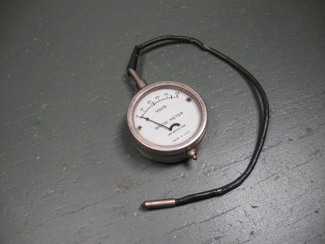
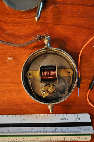
I purchased this vintage pocketwatch style voltmeter a little while ago. It's coming in the mail in a week and I'm eager to take it apart. There should be a decent amount of room in there to stuff a couple of coin cell batteries, an Arduino mini and some amplifier circuitry. The idea is to create a timepeice that ticks off the seconds, minutes, and hours with a simple little pwm shifter I wrote.

The prototype I've made with a 1-5v meter works well and looks a bit like http://hackaday.com/2009/11/12/too-much ... -pressure/

Code: Select all

/*
Voltmeter Clock - Code by Matthew Borgatti ***http://sinbox.org***

*/

int secondValue = 0;
int minuteValue = 0;
int hourValue = 0;
int clockPin = 9;                                 //The input lead for the voltmeter. Connect the other lead coming from the meter to ground
int voltRange = 125;                              //voltRange defines the maximum operating voltage of your meter (max = 255 ~5v)
int voltVal = voltRange / 60;
int minutes = voltRange / 60;
int hours = voltRange / 12;
int value = 0;                                    //value is a container for the current voltage
int switch1 = 10;                                 //The input pin for the minute setting switch
int switch2 = 11;                                 //The input pin for the hour setting switch
int pingPong = 0;                                 //Setting pingPong to 1 will have the second hand pingpong between 0 and 255

void setup() 
{ 
  Serial.begin(9600);
} 
 
void loop() 
{ 
  for(value = 0 ; value <= voltRange; value += voltVal) // fade in (from min to max) 
  { 
    secondValue += 1;
    if(secondValue % 10 == 0)
    {
      int curHours = hours * hourValue;
      analogWrite(clockPin, curHours);
      delay(1000);
      value += voltVal;
      int curMinutes = minutes * minuteValue;
      analogWrite(clockPin, curMinutes);
      delay(1000);
      value += voltVal;
      secondValue += 2;
    }
    if(secondValue > 59)
    {
      secondValue = 0;
      minuteValue += 1;
    }
    if(minuteValue > 59)
    {
      minuteValue = 0;
      hourValue += 1;
    }
    if(hourValue > 11)
    {
      hourValue = 0;
    }
    if(value >= voltRange)
    {
      value = 0;
    }
    analogWrite(clockPin, value);           // sets the value (range from 0 to 255) 
    delay(1000);                            // waits for 30 milli seconds to see the dimming effect 
  } 
  for(value = voltRange; value >=0 && pingPong == 1; value -= voltVal)   // fade out (from max to min) 
  { 
    secondValue += 1;
    if(secondValue % 10 == 0)
    {
      int curHours = hours * hourValue;
      analogWrite(clockPin, curHours);
      delay(1000);
      value += voltVal;
      int curMinutes = minutes * minuteValue;
      analogWrite(clockPin, curMinutes);
      delay(1000);
      value += voltVal;
      secondValue += 2;
    }
    if(secondValue > 59)
    {
      secondValue = 0;
      minuteValue += 1;
    }
    if(minuteValue > 59)
    {
      minuteValue = 0;
      hourValue += 1;
    }
    if(hourValue > 11)
    {
      hourValue = 0;
    }
    analogWrite(clockPin, value);           // sets the value (range from 0 to 255) 
    delay(1000);                            // waits for 30 milli seconds to see the dimming effect 
  } 
} 
As you can see from the photo the voltmeter has a range from 0-50v. Now, my question is how to set up the electronics to boost the input voltage all the way to 50v, to get the full range out of the voltmeter, while still having the same kind of precision control to get a good ticking clock animation. I'm decent at code but rather BANNED with electronics unless everything is laid out pretty simply. Is there a discrete IC that could take care of the voltage amplification? Should I be looking for DC-DC converters or op amps or flyback transformers or something else?

I'd also like to know more about sleep functions that might exist for the Arduino. It would be nice to be able to conserve battery by having the clock keep the current time in memory in a shutdown mode until its woken up by a signal from an accelerometer or a button press to count out the time on the dial.

Thank you for reading. Rock on.

User avatar
zener
 
Posts: 4567
Joined: Sat Feb 21, 2009 2:38 am

Re: Voltmeter Pocket Watch

Post by zener »

The issue is going to be: what is the input impedance of this meter? Put another way, how much current will it draw? You want quite a boost, 3V to 50V. That is a boost of about 17x. That means that whatever current the meter needs (which could be a lot for that old meter), you divide that by the efficiency (yielding a larger number) then multiply that by 17. It is quite possible that the batteries will not be able to do the job, or at least not for very long. Anyway, Maxim has a couple of parts that boost that high, or you can look at voltage multiplier circuits. But I would figure out the meter input impedance first.

http://www.maxim-ic.com/app-notes/index.mvp/id/1109

Linear Tech has a bunch of parts that might work also.

It is interesting, those guys are still in business:

http://www.beede.com

User avatar
gianteye
 
Posts: 10
Joined: Sat Jan 02, 2010 1:18 am

Re: Voltmeter Pocket Watch

Post by gianteye »

@Zener Thank you for the advice. It is pretty cool that they're still up and running. I think I'll give them a call once I've got the little meter to see if they can give me some history about the model.

Would it be unreasonable to start with 12 or more volts with some coin cells and then have it scaled through a boost converter? I was considering having a series of coin cells totaling maybe 12v, boosting it to 50v with a DC-DC transformer and creating a pwm signal from a mosfet triggered by the arduino pwm. Am I on the right track or will I hit major problems with this method?

http://www.flickr.com/photos/gianteye/4238587298/ - I also made a video of an early prototype in action if you'd like to check it out.

User avatar
zener
 
Posts: 4567
Joined: Sat Feb 21, 2009 2:38 am

Re: Voltmeter Pocket Watch

Post by zener »

Your approach is correct. It is just a matter of power calculations. Once you know the resistance of the meter then you can figure out what will work, and for how long.

RJM
 
Posts: 4
Joined: Fri Dec 18, 2009 3:27 am

Re: Voltmeter Pocket Watch

Post by RJM »

Generally analog meters of this type are actually current meters and have a resistor in series to measure volts. I suspect that because of the age it is probably a 1ma meter movement with a 50k series resistor. You will just have to calculate the value of the replacement resistor to give you the correct value for the voltage you have to read full scale. 50K is just a guess for the value of the resistor in series with the meter movement in the pocket watch meter that you are buying. You will need to measure the value of the resistor and divide 50V by that value to get the full scale current value of the meter movement.

User avatar
gianteye
 
Posts: 10
Joined: Sat Jan 02, 2010 1:18 am

Re: Voltmeter Pocket Watch

Post by gianteye »

One of my meters just arrived today.

Image
http://www.flickr.com/photos/gianteye/s ... 031313495/

The mechanism is as simple as could be. There's just a magnetic coil that moves the lever arm across the dial. The resistance of the coil is 164.8ohms. There is no resistor in the unit.

I'm still unsure of exactly how to proceed but I'm slowly calculating the values for the parts I need. If you'd like you can take a look at some of the schematics I've drawn up here: http://sinbox.org/voltmeter%20clock.sch, http://sinbox.org/voltmeter%20clock.bmp

User avatar
zener
 
Posts: 4567
Joined: Sat Feb 21, 2009 2:38 am

Re: Voltmeter Pocket Watch

Post by zener »

So lets see, 50V/165 = 303mA, /.8 efficiency = 379 mA, x4 boost (12 to 48) = 1.5A. Can your button cells deliver that? I realize you do not need 50V all the time, but even averaging at 25 that is 750mA.

User avatar
gianteye
 
Posts: 10
Joined: Sat Jan 02, 2010 1:18 am

Re: Voltmeter Pocket Watch

Post by gianteye »

Looking up the specs on even the most 1337 batteries I still can't push 750ma. I was hoping to use a e23a 12v medical battery but it can't hurl out that kind of current. It looks like this project might have to be tethered to a few batteries and an arduino mini packed in an altoids tin.

User avatar
Franklin97355
 
Posts: 23939
Joined: Mon Apr 21, 2008 2:33 pm

Re: Voltmeter Pocket Watch

Post by Franklin97355 »

Since you plan to make this into something it never was I would recommend you gut the inside keeping the face and hand and find a small stepper or servo to move the hand. when not moving the hand you could put all but the rtc to sleep and save energy.

User avatar
zener
 
Posts: 4567
Joined: Sat Feb 21, 2009 2:38 am

Re: Voltmeter Pocket Watch

Post by zener »

franklin97355 wrote:Since you plan to make this into something it never was I would recommend you gut the inside keeping the face and hand and find a small stepper or servo to move the hand. when not moving the hand you could put all but the rtc to sleep and save energy.
Yes. Or at least a more sensitive analog movement. Another issue is how much space is really available? You might run out of room fast when you actually try putting everything in. So put in the motor recommended, or a low voltage modern movement.

User avatar
gianteye
 
Posts: 10
Joined: Sat Jan 02, 2010 1:18 am

Re: Voltmeter Pocket Watch

Post by gianteye »

I'm hoping to use a motor to drive the needle only as a last resort. I've decided to use an external housing to keep all the electronics as there's just no way to cram everything I need in there. Besides, the case is even too small to cram in an Arduino Nano Pro.

If I was struck with the sudden desire to replace the coil with a more efficient one, how would I go about it. Is there a good reference on how to make a coil and measure its efficiency?

User avatar
zener
 
Posts: 4567
Joined: Sat Feb 21, 2009 2:38 am

Re: Voltmeter Pocket Watch

Post by zener »

Maybe get something like this:

http://www.jameco.com/webapp/wcs/stores ... tId=315301

and put the movement in your case, and you would have to attach your indicator somehow. As you can see, it is very sensitive. You could run it off of 3.3V for example. In that case I think you would put a series resistor of about 65K. It might have trouble swinging that heavy arm though. You might be able to paint the meters arm to make it look older. You will feel like a watchmaker if you can figure this out.

Locked
Please be positive and constructive with your questions and comments.

Return to “General Project help”