Hi,
We are students from Central Michigan University, and are working with the polar starter kit. We were wondering if there is a step-by-step guide for beginners in regards to the construction of the receiver and the breadboard. We are beginners working with these electronics and would like some help. Even a realistic photograph would give us a good idea where to go.
Thanks
Polar starter kit
Moderators: adafruit_support_bill, adafruit
Please be positive and constructive with your questions and comments.
-
adafruit_support_bill
- Posts: 88154
- Joined: Sat Feb 07, 2009 10:11 am

Re: Polar starter kit
There is a link to the Parallax tutorial page under the "Tutorials" tab: http://www.adafruit.com/products/1077#Learn
-
cmuapparel
- Posts: 8
- Joined: Mon Mar 31, 2014 9:16 am
Re: Polar starter kit
Unfortunately, this tutorial isn't helpful to us, being beginners without any knowledge of electronics. The language and diagrams are beyond our understanding. Is there a place where the steps are broken down in a more simpler fashion.
Another concern is that the tutorial makes it seem like we don't have the right parts included in the starter kit. Is there anything else we need to make this work?
If you know of any forum that deals with beginners using this particular kit, we would be appreciative. All the one's we seem to find are for more advanced projects than the one we are doing.
Thank You
-
adafruit_support_bill
- Posts: 88154
- Joined: Sat Feb 07, 2009 10:11 am
Re: Polar starter kit
Are you sure you are looking at the Parallax tutorial link? http://learn.parallax.com/KickStart/28048The language and diagrams are beyond our understanding.
The Parallax tutorial is pretty basic. It just shows you how to connect it to your microcontroller and provides some sample code to take basic readings.
If you describe what you are trying to do and what parts of the tutorial you don't understand, maybe we can help.
-
cmuapparel
- Posts: 8
- Joined: Mon Mar 31, 2014 9:16 am
Re: Polar starter kit
The page appears to be correct.
Can I just get a confirmation of what parts we will need to assemble the receiver piece? The tutorial mentions products that were not included in the starter kit. That seems to be causing some of the confusion.
Once we get that, we will try and go from there.
Thanks For Your Help!
Can I just get a confirmation of what parts we will need to assemble the receiver piece? The tutorial mentions products that were not included in the starter kit. That seems to be causing some of the confusion.
Once we get that, we will try and go from there.
Thanks For Your Help!
-
adafruit_support_bill
- Posts: 88154
- Joined: Sat Feb 07, 2009 10:11 am
Re: Polar starter kit
Which parts specifically? Please explain what you are trying to build with this receiver.The tutorial mentions products that were not included in the starter kit. That seems to be causing some of the confusion.
The tutorial assumes that you have a microprocessor of some sort. It is petty flexible about what type you use. It also assumes that you have some wire and some basic tools to make connections from the receiver to your microprocessor.
-
splatten
- Posts: 439
- Joined: Mon Mar 17, 2014 3:08 pm

Re: Polar starter kit
The receiver has three pins on one side and three pads on the other, the top of the board has a small '+' above the top pad, the bottom pad is the negative, the pad in the middle is the signal pulse.
Just connect 5V to the top pad, 0 to the bottom and connect the middle pad to a digital input.
Just connect 5V to the top pad, 0 to the bottom and connect the middle pad to a digital input.
-
cmuapparel
- Posts: 8
- Joined: Mon Mar 31, 2014 9:16 am
Re: Polar starter kit
Thank You SPlatten
That makes a little more sense.
The question we now have is where do we place the LED light and the resistor in the breadboard.
Thanks again for your help.
That makes a little more sense.
The question we now have is where do we place the LED light and the resistor in the breadboard.
Thanks again for your help.
-
splatten
- Posts: 439
- Joined: Mon Mar 17, 2014 3:08 pm
Re: Polar starter kit
You could connect the positive side of the LED to the pulse output and the other side to GND. The LED will then flash for every pulse.
-
cmuapparel
- Posts: 8
- Joined: Mon Mar 31, 2014 9:16 am
Re: Polar starter kit

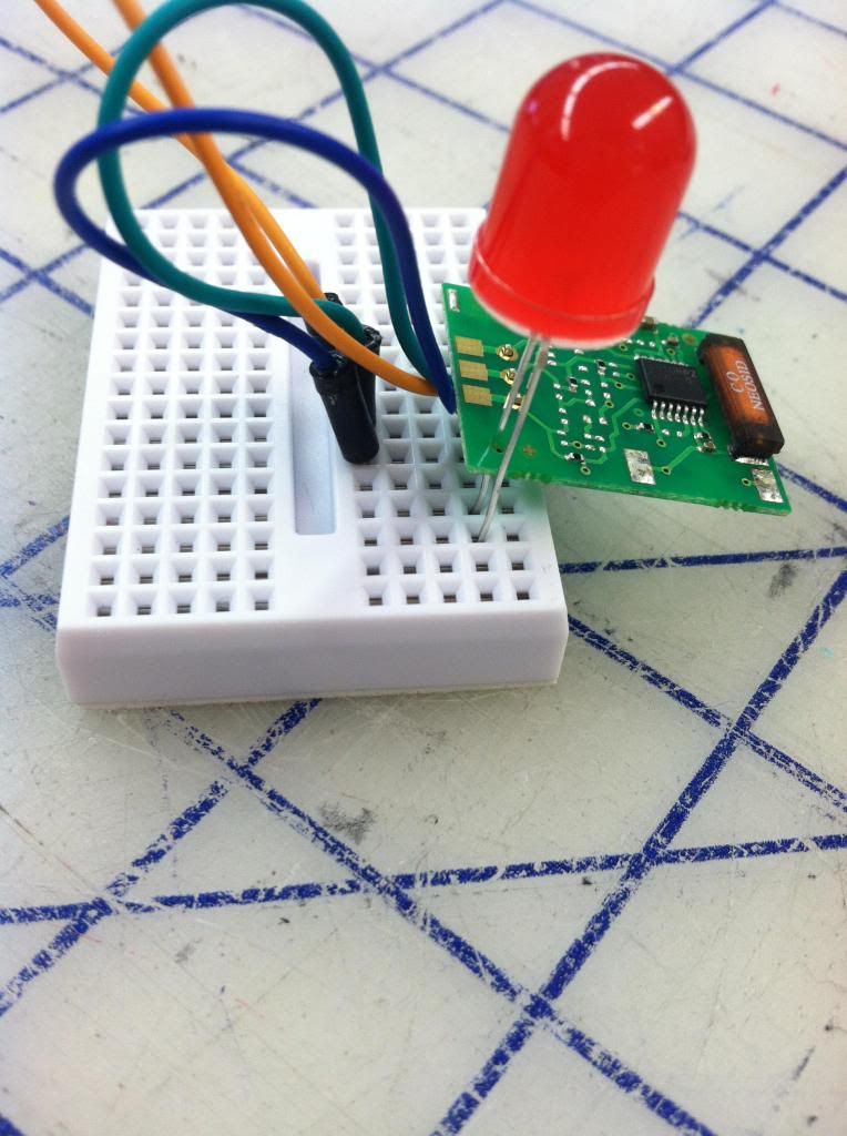
This is where we are in the process. Does this setup look correct. We are waiting to attach the battery pack until the end.
-
adafruit_support_bill
- Posts: 88154
- Joined: Sat Feb 07, 2009 10:11 am
Re: Polar starter kit
The connections in that breadboard run in horizontal rows. In the current configuration, nothing is connected. For two wires or pins to be connected, they have to be plugged into the same row on the same side of the breadboard.
You should connect the long pin on the LED to the positive pin on the board. Connect the short pin to one end of a resistor (220ohms would be a good size) and connect the other end of the resistor to the digital output pin on the board.
You should connect the long pin on the LED to the positive pin on the board. Connect the short pin to one end of a resistor (220ohms would be a good size) and connect the other end of the resistor to the digital output pin on the board.
-
cmuapparel
- Posts: 8
- Joined: Mon Mar 31, 2014 9:16 am
Re: Polar starter kit
Is this new setup correct?
Can you give us a quick map of the layout of the receiver. We seem to be confused with which pins we are connecting to the LED and the resistor?
Thanks again for all of your help!

Can you give us a quick map of the layout of the receiver. We seem to be confused with which pins we are connecting to the LED and the resistor?
Thanks again for all of your help!
-
adafruit_support_mike
- Posts: 67485
- Joined: Thu Feb 11, 2010 2:51 pm

Re: Polar starter kit
You have the correct orientation on the breadboard, but you need to solder the pin header into the PCB for the connections to work.
The LED doesn't seem to be connected to anything though.
The LED doesn't seem to be connected to anything though.
-
cmuapparel
- Posts: 8
- Joined: Mon Mar 31, 2014 9:16 am
Re: Polar starter kit
Glad we are making progress.
Thanks!
Which pins should the LED connect with? There seems to be a couple different options available.adafruit_support_bill wrote:
You should connect the long pin on the LED to the positive pin on the board. Connect the short pin to one end of a resistor (220ohms would be a good size) and connect the other end of the resistor to the digital output pin on the board.
Thanks!
-
adafruit_support_bill
- Posts: 88154
- Joined: Sat Feb 07, 2009 10:11 am
Re: Polar starter kit
Connect the long pin to the pad marked with the +
Connect the short pin to one end of the resistor.
Connect the other end of the resistor to the center pad.
Connect the short pin to one end of the resistor.
Connect the other end of the resistor to the center pad.
Please be positive and constructive with your questions and comments.