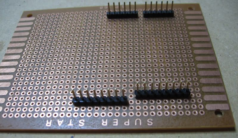
Now that spacing between the two headers, where pin 7 and pin 8 are, can be a source of frustration, can’t it? If only it was a 100 mil (0.1″ or 2.54 mm) spacing, just like the spacing of all the other pin headers. Then you could make a quick and cheap “shield” board using 100-mil-grid matrix board or veroboard, and use all the digital IO pins, for example.
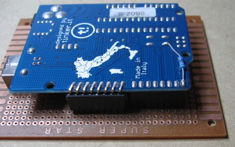
Well, what I did was to take a strip of 100-mil female right-angle header... it must be right angle. Now, cut off a piece that is 8 pins long (or buy a pre-cut piece of 8 pins?). Apply a bit of glue - cyanoacrylate superglue is good, but read the next bit first - you'll need to know what you're doing once the glue goes on
Now, we’re going to slide the new pin header across just a little bit, towards pin 13, so that the horizontal spacing between the first pin (next to pin 8 ) on the new header and the existing pin 7 on the other header is exactly 0.2 inches.
I found that the easiest way to make the assembly stay together in the right position while the glue cures is to first make up a little Arduino daughterboard “shield”, using a piece of 0.1″ matrix board and 0.1″ male header pins. Plug the Arduino (including the newly installed header) onto the daughterboard, and the new header will stay in place, without moving away from the correct 0.1″ spacing, while the glue cures.
Now, on the bottom of the Arduino PCB, we need to bend the pins on the bottom of the header across just a touch, so they align with the existing solder pads on the original female header. Then we simply solder them on, and there you go.
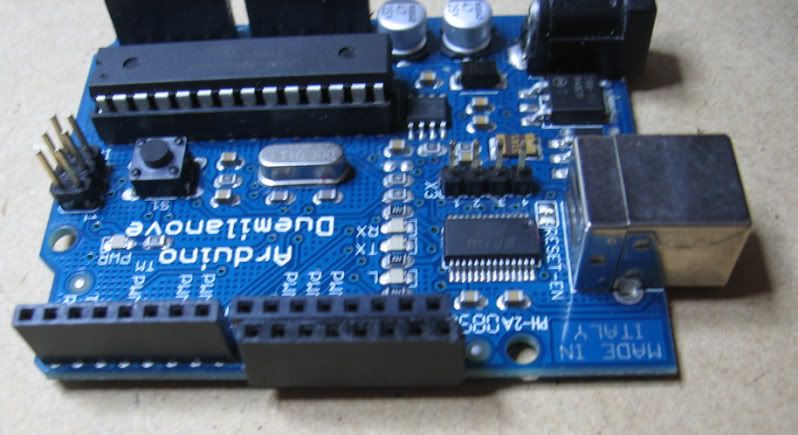
(Note that I’ve added a 100 k pull-down resistor on the Rx line (pin 0). I haven’t tested this yet, but hopefully it will let the Arduino boot up successfully without the USB interface connected, without it getting confused due to the line floating. Also note that I’ve added header pins onto the normally unpopulated pads on the PCB near the FTDI chip, bringing out the spare UART handshake lines from the FTDI. I’m not sure what this is good for right now, but I thought I might as well do it while I was attacking the Arduino with a soldering iron.)
We now have an Arduino with headers that are all accessible on an 0.1″ grid spacing. Of course, we can still plug “real” Arduino shields, with the default spacing, into the original headers as well, so we haven't broken compatibility with anything.