pn532 shield schematic
Moderators: adafruit_support_bill, adafruit
Please be positive and constructive with your questions and comments.
-
al_b
- Posts: 4
- Joined: Sun Nov 09, 2014 12:48 pm

pn532 shield schematic
The schematic for the pn532 breakout board is available, but apparently not for the pn532 shield. When will this schematic be available?
-
adafruit_support_bill
- Posts: 88154
- Joined: Sat Feb 07, 2009 10:11 am

Re: pn532 shield schematic
It's here in gthub: https://github.com/adafruit/Adafruit-PN ... NFC-Shield
-
al_b
- Posts: 4
- Joined: Sun Nov 09, 2014 12:48 pm
Re: pn532 shield schematic
Thanks, but these files produce the following error in Eagle v.7.1:
Loading /home/allan/Adafruit_PN532_Shield_v1.0.sch ...
Error:
line 6, column 25: This is not an EAGLE file.
The breakout board schematic renders perfectly.
Loading /home/allan/Adafruit_PN532_Shield_v1.0.sch ...
Error:
line 6, column 25: This is not an EAGLE file.
The breakout board schematic renders perfectly.
-
al_b
- Posts: 4
- Joined: Sun Nov 09, 2014 12:48 pm
Re: pn532 shield schematic
Oops, my mistake. I downloaded the link instead of the file. Ha!
Thanks for your help.
Thanks for your help.
-
al_b
- Posts: 4
- Joined: Sun Nov 09, 2014 12:48 pm
Re: pn532 shield schematic
If one is not familiar with grabbing the correct file from this source, the trick is to click the link to the schematic or board file and then on the new page, click "View Raw". Save the file. Open this file with Eagle. Success!
-
Franklin97355
- Posts: 23940
- Joined: Mon Apr 21, 2008 2:33 pm

Re: pn532 shield schematic
You can also download the zip file, open that and click on the file you want to view. It will open in Eagle even without unzipping the entire folder, at least in winzip it does for me.
-
ab_au
- Posts: 3
- Joined: Thu Aug 03, 2017 1:25 am

Re: pn532 shield schematic
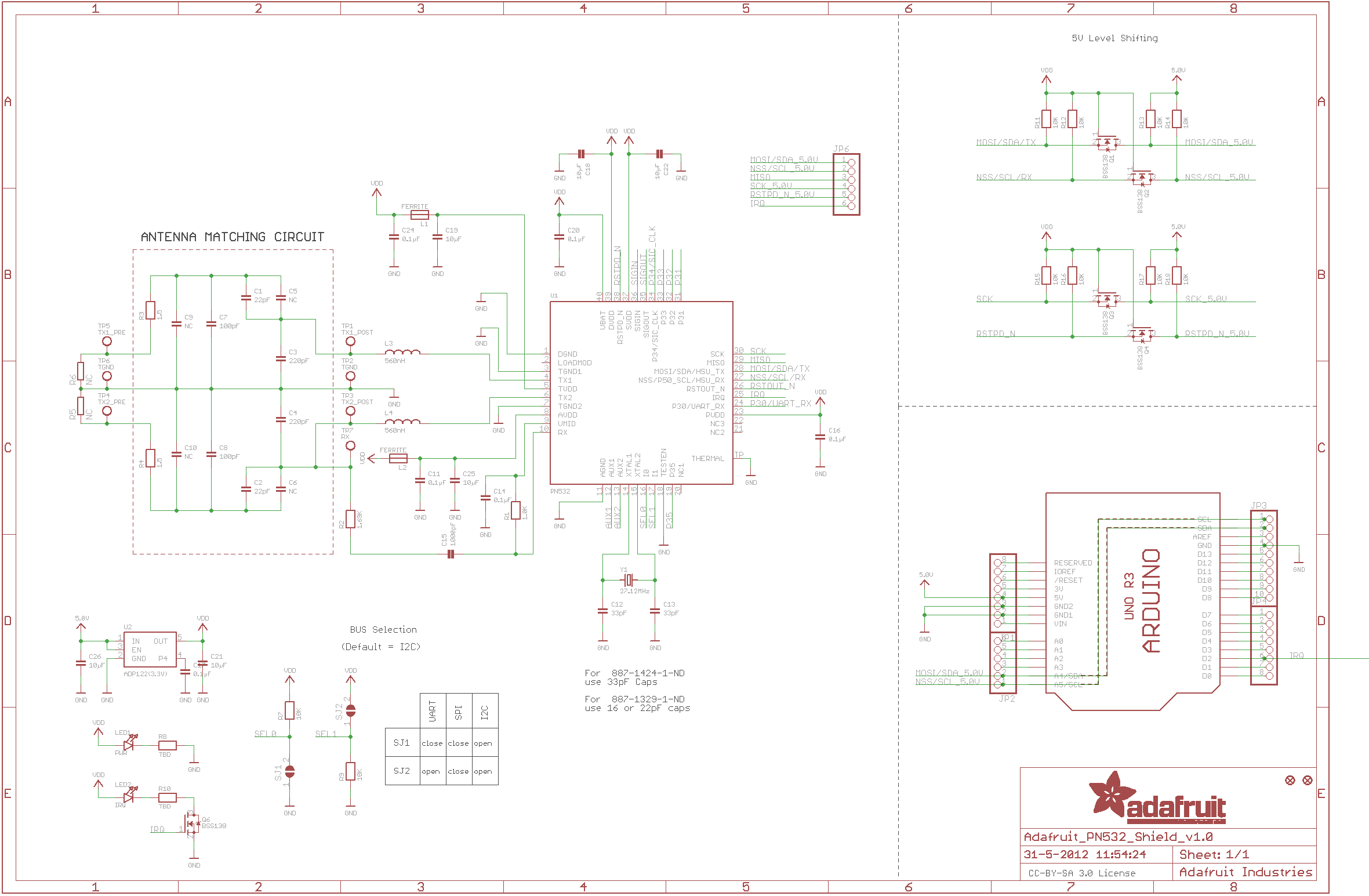
Is anyone able to share an image of this PN532 Arduino shield's schematic?
I'm not eligible for a free Eagle license...
All I really want to know is:
- are the SPI pins connected to the Arduino headers?
- if yes, to what pins?
I have found an image of the v1.0 board, where the SPI pins were not connected (well, half of them are, by virtue of being shared between I2C and SPI).
I don't know what changed between v1.0 and 1.3 though, hopefully the SPI was added? (wishful thinking)
Here's the schematic I found, in case any future forum archaeologists are looking for the same thing:
https://www.mobilefish.com/images/devel ... ematic.png
Please be positive and constructive with your questions and comments.