
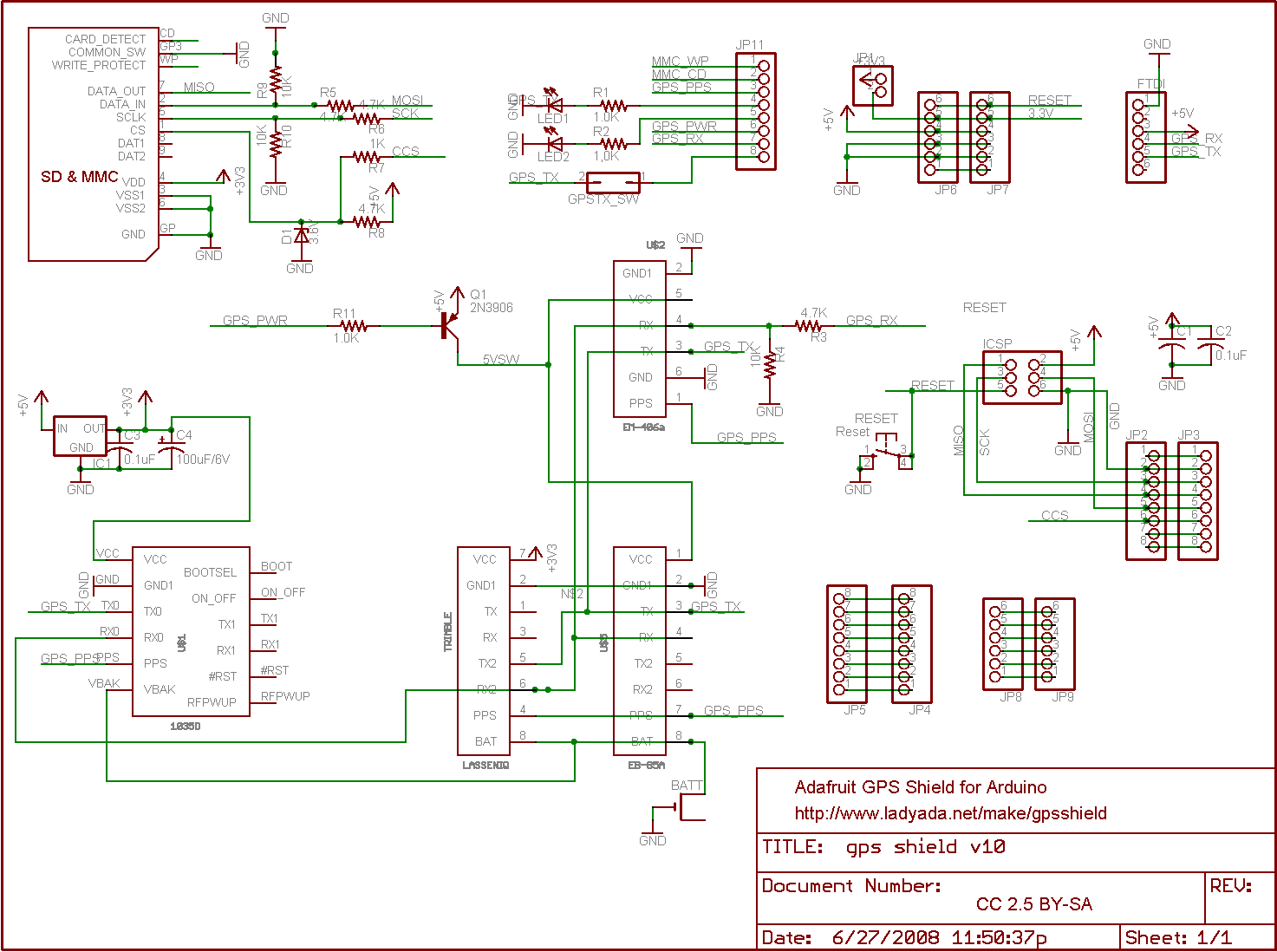
some questions, im having trouble orienting myself to the schematic at http://www.ladyada.net/make/gpsshield/g ... 10_sch.png :
using the image at http://farm4.static.flickr.com/3058/261 ... f31fc7.jpg as reference,
JP4 and JP5 are located left bottom of the board?
JP2 and JP3 are located middle bottom of the board?
JP1 ...basically i cant find any silk screening on the board that corresponds with any of the jumpers so im lost. can you help?
thanks.
Reading the GPS shield schematic
Moderators: adafruit_support_bill, adafruit
Please be positive and constructive with your questions and comments.
Please be positive and constructive with your questions and comments.