
I'm trying to get a more intense infrared signal, and I was wondering if I could replace the Everlight IR-333A LEDs that come in the kit with these other ones: Osram SFH4544. It seems that they are similar in terms of optical wavelength, beam pattern, acceptable current (100+ mA), forward voltage, etc, but the SFH4544 specs say it puts out 550 mW/sr, compared to 85 mW/sr for the IR-333A.
Any reason I couldn't just swap out the IR-333A LEDs with SFH4544 and get a much stronger optical signal?
The spec sheets are:
IR-333A: http://www.everlight.com/file/ProductFi ... 067600.pdf
SFH4544: https://dammedia.osram.info/media/resou ... 204544.pdf
Could I use these IR LEDs instead?
Moderators: adafruit_support_bill, adafruit
Please be positive and constructive with your questions and comments.
-
adafruit_support_bill
- Posts: 88155
- Joined: Sat Feb 07, 2009 10:11 am

Re: Could I use these IR LEDs instead?
Looks like it should work. Newer designs tend to be more efficient. But 3x is quite an improvement.
-
WindyDay
- Posts: 33
- Joined: Sun Dec 22, 2019 10:20 pm
Re: Could I use these IR LEDs instead?
Hi Bill,
Thanks! I'll give that a try. One other question, if you don't mind: is there any reason I couldn't add a bunch more NPN transistor + LED pairs (say, a total of 16 instead of 4) to crank out an even stronger optical signal? It seems like the PNP transistor could supply plenty of current for the bases of the NPNs.
Thanks! I'll give that a try. One other question, if you don't mind: is there any reason I couldn't add a bunch more NPN transistor + LED pairs (say, a total of 16 instead of 4) to crank out an even stronger optical signal? It seems like the PNP transistor could supply plenty of current for the bases of the NPNs.
-
adafruit_support_bill
- Posts: 88155
- Joined: Sat Feb 07, 2009 10:11 am
Re: Could I use these IR LEDs instead?
Yes. that PNP should be able to handle the fan-out to drive more NPNs.
You may be interested in this thread: viewtopic.php?f=23&t=4975&p=27447
If it is longer range you are looking for, people have also had good results adding optics to better focus the beam.
You may be interested in this thread: viewtopic.php?f=23&t=4975&p=27447
If it is longer range you are looking for, people have also had good results adding optics to better focus the beam.
-
WindyDay
- Posts: 33
- Joined: Sun Dec 22, 2019 10:20 pm
Re: Could I use these IR LEDs instead?
Hi Bill,
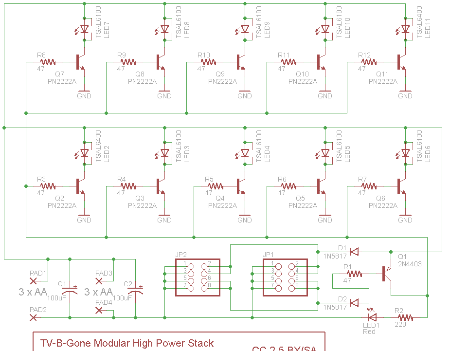
Thanks for your reply, including the link to the informative prior thread. I did go ahead and buy 6 new LEDs of model SFH4544, SFH4545, and SFH4546 (two of each), which differ among themselves only in the beam angle. I wasn't successful, and I was wondering if you or anyone else might be able to give me guidance about what I might have done wrong. I uploaded a rough circuit diagram, and can try to describe what I attempted to do...
I realized that the unused holes/pads for the optional R2 resistor on the TV-B-Gone could be used to the output from the TV-B-Gone's Q5 transistor (the PNP described as the "IR-Driver-Transistors-Driver Transistor" in the Design Notes for the TV-B-Gone kit) that is used to drive. (The R2 resistor pads seem to connect to Q5's collector and to ground,respectively.) So I soldered long wires to each of those pads to connect to a breadboard with the new components. (I used 12-inch wires because I want to be able to hang the (bread)board with the additional LEDs out a window to get better line-of-sight on my target TV. I twisted those wires because it seemed like it might be a good idea...reduce parasitic capacitance??). I connected the new LEDs to NPN transistors on the breadboard in the same way as is done on the TV-B-Gone board. I powered the breadboard with a separate 3xAAA battery pack since I figured all of this is going to draw a fair amount of current, with all of the grounds tied together. (Actually, I also tried powering the breadboard with two 3xAAA packs in parallel but that didn't seem to help.) I have the TV-B-Gone board powered by a 3xAA battery pack rather than the 2xAA pack that comes with the kit.
When I turn on both battery packs and press the reset button on the board, the LEDs on the TV-B-Gone board work as they are supposed to. (Turns my TV on/off, and when viewed with my cellphone camera I can see the LEDs flickering on/off.) However, the LEDs on the breadboard don't seem to be working. (I don't see them flickering when I view them with my cellphone camera, and if I cover up the LEDs on the TV-B-Gone board then I can't get the TV to turn off.) The TV-B-Gone board seems to get pretty hot and I smell a bit of classic burning electronics smell. I've triple-checked my circuit to make sure all the components are well-seated in the breadboard, that I didn't create a short circuit, that I connected the correct pins of each component, etc. So I'm not really sure what isn't right.
One other thing that I tried, which didn't seem to make a difference, was to add a PNP transistor (PN2907, like Q5 in the TV-B-Gone board) on the breadboard to boost the signal to the NPNs. I have no idea if this is a good idea (maybe reduce the amount of current we try to draw along the long wires between the TV-B-Gone board and the breadboard) or a bad idea.
Thanks a bunch for any ideas. And no worries if this is all too much to ask and you tell me to go back and re-read my college EE texts from 20+ years ago!
- Attachments
-
- CCF_0003.tif (622.85 KiB) Viewed 2281 times
-
adafruit_support_bill
- Posts: 88155
- Joined: Sat Feb 07, 2009 10:11 am
Re: Could I use these IR LEDs instead?
One thing I see missing in your circuit is a resistor to limit the current through the base of the PN2222.
I'd start by replicating the circuit posted by oPossum. Maybe just one additional transistor/LED to get started, then replicate that once you have it working.
I'd start by replicating the circuit posted by oPossum. Maybe just one additional transistor/LED to get started, then replicate that once you have it working.
-
WindyDay
- Posts: 33
- Joined: Sun Dec 22, 2019 10:20 pm
Re: Could I use these IR LEDs instead?
Thanks, will do. I was trying to just replicate what is done on the TV-B-Gone board, where the base of the NPN transistors are connected directly to the collector of the PNP transistor.
-
WindyDay
- Posts: 33
- Joined: Sun Dec 22, 2019 10:20 pm
Re: Could I use these IR LEDs instead?
Hi Bill,
I now seem to have it up and working, and the problem (and solution) were much simpler than thought: I had connected all 6 LEDs backwards! (Insert sheepish grin emoji here.) I had thought that the long leg of an LED was always the anode, but apparently not always. On these Osram IR LEDs (SFH4544, SFH4545, SFH4546) it turns out the long leg is the cathode. Now with my cellphone camera I can see the LEDs firing, and a test on my TV at home works fine. The weather is warm, so chances are that at some point soon my obnoxious neighbor will fire up his outdoor TV at high volume and I'll have a chance to test out my gizmo!
Thanks again.
-
adafruit_support_bill
- Posts: 88155
- Joined: Sat Feb 07, 2009 10:11 am
Re: Could I use these IR LEDs instead?
Good to hear you have it working. And good luck with silencing the offensive TV. :)
Please be positive and constructive with your questions and comments.